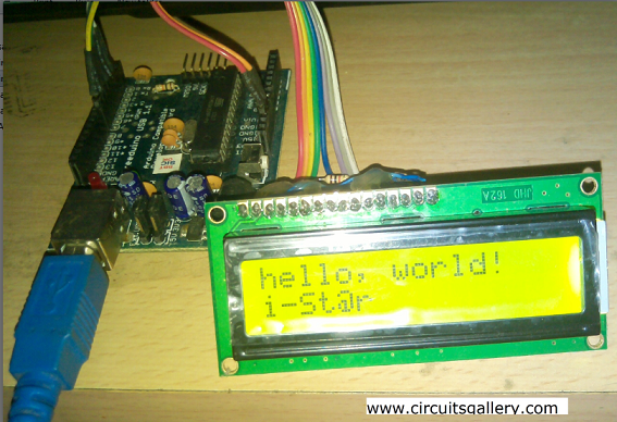
Arduino 16×2 LCD Tutorial: Interfacing LCD with Arduino Hello World
As you know, LCDs are widely used in projects and various products in order to display the processes and output values. Furthermore, we have decided to publish many Arduino LCD projects in the upcoming weeks. So it’s a prerequisite to have good knowledge of interfacing LCD with Arduino before we move on further.
We have already published a detailed post on LCD interfacing with PIC microcontrollers a long time ago when we were discussing the basics of PIC microcontrollers. You may refer to that for a deeper understanding of the 2×16 LCD display including the various pins involved.
In contrast to many other microcontroller platforms, Arduino LCD control is very simple as it has many inbuilt library functions. You only need to initialize the pins for connecting the LCD display to Arduino and define the LCD type- number of columns and rows.
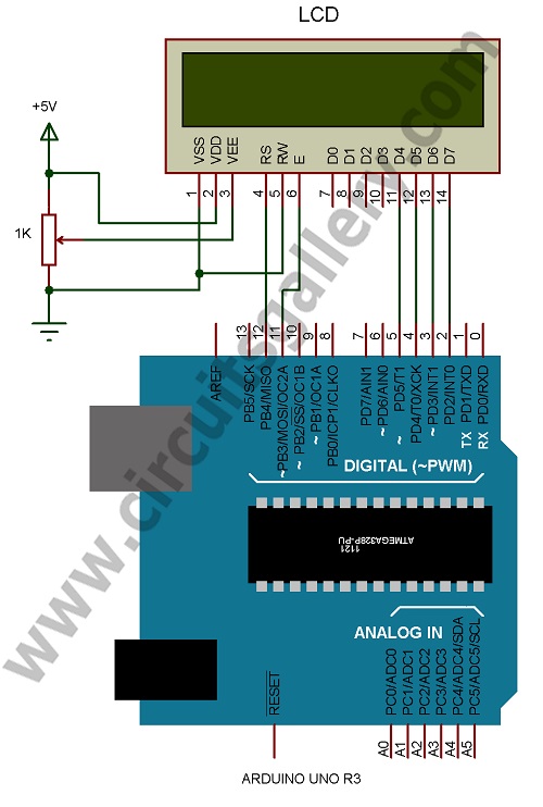
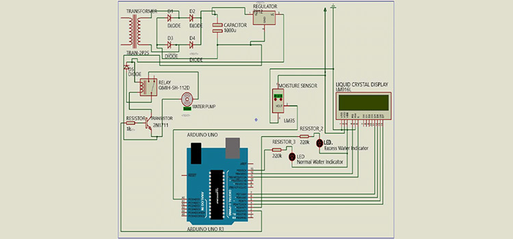
Circuit Schematic
Components Required
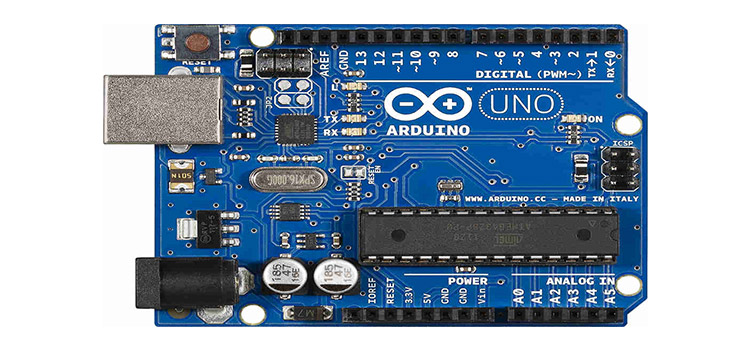
- Arduino Board
- LCD
- Resistor 1K
Working
- LCD can be used in two modes- 4-bit mode or 8-bit mode. In 8-bit mode, we require 8 data pins and 3 control pins whereas, in 4-bit mode, data is sent using 4 data pins and 3 control pins.
- R/W pin is always grounded so we require only 6 pins in 4-bit mode, thus saving no of pins.
- First, initialize the library and then define pins using the command LiquidCrystal LCD(RS, E, D4, D5, D6, D7), pins are assigned in this order.
- LiquidCrystal LCD(12, 11, 5, 4, 3, 2), here RS pin to 12, Enable pin to 11, D4 pin to 5, D5 pin to 4, D6 pin to 3, and D7 pin to 2 respectively.
- Then in the setup function write the message to display as lcd.print(“message”).
- We can print messages anywhere in the LCD by selecting column and row, it’s done by writing lcd.setCursor(column, row). However there is one thing to consider, that’s the number of columns and rows starting from zero. For example, to print a message on the 2nd row 1st column, write “lcd.setCursor(0,1);” before the print command. Similarly, for the 5th column and 3rd row, we write lcd.setCursor(4,2).
- You can use “lcd.write()” to send characters. To print zero on 2nd colum 2nd row, type lcd.setCursor(1,1); lcd.write(48); where 48 is the decimal equivalent for ACII ‘0’.
Interfacing LCD With Arduino Programming
Let’s summarize our program in the following steps.
Step1: Initialize the library for LCD.
Step2: Define LCD columns and rows in the setup function.
Step3: Write the data to display.
Step4: If you want to display variables on LCD, write it in the loop function. The loop function is a must for all Arduino sketches.
| 1 2 3 4 5 6 7 8 9 10 11 12 13 14 15 16 17 18 | #include // initialize pins LiquidCrystal lcd(12, 11, 5, 4, 3, 2); void setup() { // Define LCD’s number of columns and rows: lcd.begin(16, 2); // Print a message to the LCD. lcd.print(“hello, world!”); lcd.setCursor(0,1); lcd.print(“i-St@r “); } void loop() { } |
Conclusion
After all, I hope you realized how things are getting easier with Arduino. This article will guide you to make more sophisticated projects with Arduino.
Subscribe to our newsletter
& plug into
the world of circuits