How to Make a Burglar Alarm Circuit for Your Home Security?
These days home security systems are given great importance everywhere. However, these security automation systems are very expensive to implement. Here I will help you to make a simple IR security system on your own using an Infrared-photodiode pair.
Earlier we had already published another intruder alarm circuit diagram which was based on LASER and LDR. However, it has a probability that the thief might see the LASER beam and avoid the theft alarm easily. This simple circuit will give you an insight into how to do burglar alarms work.
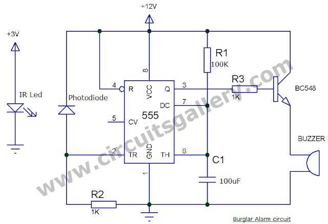
Simple Burglar Alarm Circuit Diagram
Components Required
- 555 timer IC
- Photodiode
- IR led
- Transistor BC 548
- 12v Buzzer
- Resistor (100K, 1Kx 2)
- Capacitor (100uf).
Working Principle of the Infrared Alarm Circuit
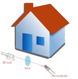
- The main component used here is a photodiode and IR led. We are creating a continuous loop arrangement around the house with it.
- The 555 timer used here works in the monostable mode of operation. You can learn more about 555 monostable multivibrators working from our previous posts.
- IR led continuously strikes infrared beams on the photodiode. As a result, the trigger pin (2nd pin) of 555 will get the positive voltage from Vcc. Hence its output will remain LOW as the 555 monostable multivibrator gets a HIGH output only on the negative trigger.
- When an intruder cuts the IR beam, photodiodes act as an open circuit. Thus 2nd pin gets negative through resistor R2 turning the monostable output to HIGH.
- The output pin is connected to the base of an NPN switching transistor through a resistor R3. Thus the transistor becomes ON giving power to the buzzer.
- In case you need to ON some light bulbs or make a much more powerful alarm bell, then you have to connect a relay instead of the buzzer.
- To increase the range of IR you can use a converging lens. How would you see if the IR beam has converged to the photodiode efficiently? For that, you can use a camera or a visible LED to set the focus and then replace that with IR LED.
- Another method to increase the range is to use a series photodiode arrangement.
- You can use two 1.5 batteries (AA-size) to power the IR led.
- Photodiode should be connected in reverse bias mode (i.e. anode to negative and cathode to positive). Then it conducts when IR beams hit on it, else it acts as an ordinary diode.
Conclusion
As you are curious enough to look for how to make a burglar alarm circuit, you must have dealt with a handful of sensors. This IR sensed mechanism can be replaced with any other sensor in more innovative projects.
Subscribe to our newsletter
& plug into
the world of circuits


