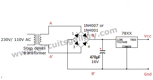
Bridge Rectifier Regulated Lab Power Supply Circuit Schematics Using 78XX Voltage Regulator
A good regulated AC to DC power supply circuit is essential for any electronic hobbyists and electronic students to do their electronics hobby projects. Also, a bridge rectifier power supply is one of the introductory circuits for beginners.
Firstly we need to know what is a bridge rectifier? A rectifier circuit employs the conversion of AC voltage to DC voltage. Full-wave bridge rectifiers have the benefit that they transfer both half cycle of AC input into DC output and also efficiency is two times greater than that of a half-wave rectifier. Bridge rectifier circuits are put into practice using diodes such as 1N4001, 1N4007, etc.
Below is the circuit schematic of bridge rectifier regulated lab power supply circuit using 78XX voltage regulator IC. 78XX is a positive voltage regulator and available at different output voltages as 7805 for 5V, 7809 for 9V, 7815 for 15V, etc. Hence you can implement power supplies for required voltages, that is 5V, 9V, or 15V as you like. Solder this regulated power supply circuit on PCB and enclose it in a suitable case, definitely, it will help you for future circuit projects.
Circuit diagram of Bridge Rectifier Power Supply Circuit Using 78XX IC
Components Required
- Step down transformer (1A, 230V or 110V primary secondary should be your choice like 6V, 9V etc).
- Diodes x 4 (1N4001 for low power 1N4007 for moderate power)
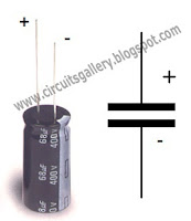
- Capacitor (470µF, 16V)
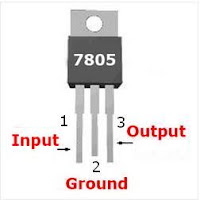
- Voltage regulator IC 78XX (Here we have used 7805)
Working Principle of Bridge Rectifier Regulated Lab Power Supply Circuit
- Circuit consists of 4 parts: Step down transformer, bridge rectifier, capacitor filter and voltage regulator IC.
- The transformer step downs the high voltage AC to a low voltage AC.
- During the positive half cycle of secondary voltage, diodes D2 and D3 are forward biased and diodes D1 and D4 are reverse biased, now the current flows through D2–>Load–>D3
- During the negative half cycle of the secondary voltage, diodes D1 and D4 are forward biased and diodes D2 and D3 are reverse biased Now the current flows through D4–>Load–>D1
- In both the cycles load current flows in same direction, hence we get a pulsating DC voltage across the points B-B’.
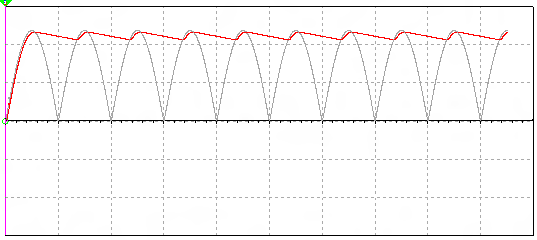
- The pulsating content are called ripples and a filter capacitor is used to remove the ripples from pulsating DC.
- When the instantaneous values of pulsating DC voltage increases, the capacitor gets charged up to peak value of the input.
- When the instantaneous values of pulsating DC voltage decreases, the stored voltage in the capacitor reverse biases the diodes D2 and D4. Hence it will not conduct, now capacitor discharges through the load. Then voltage across the capacitor decreases.
- During the next cycle, when the peak voltage exceeds the capacitor voltage, diode D2 or D4 forward biases accordingly, as a result capacitor again charges to the peak value. This process continues. Hence we get almost smooth DC voltage as shown.
- Then the filtered voltage is applied to the input of 7805 voltage regulator IC, it in turn regulates the voltage for line and load fluctuations.
The brown color indicates pulsating DC and the red color is the filtered DC voltage. Basically, the brown color indicates capacitor output DC and the red color is the regulated 5V DC from 7805.
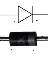
Pinouts of Diode, Capacitor and 7805 IC
Conclusion
While building the bridge rectifier regulated lab power supply circuit you’ll have to use a 6V secondary transformer and 7805 for a 5V supply. Alternatively, 9V secondary transformer should be used along with a 7809 for 9V supply.
Subscribe to our newsletter
& plug into
the world of circuits