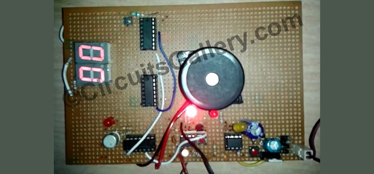
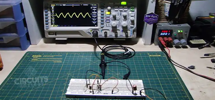
Clap Switch Circuit Using 555
Snap your fingers to let happen what you want! Yes, that’s what we have ahead: at least in the realm of electrical and electronic appliances. I’ve used 555 timer to avail the monostable multivibrator functionality and 7474 D-flip flop to hold the signal.
Of course it’ll pick the signal using a condenser mic. The relay will help you use the output of the clap switch circuit using 555 to any project.
Clap Switch Circuit Using 555
Components of Clap Switch Circuit
- Bridge Rectifier (Step Down Transformer, Diodes-4, Capacitor 470μF)
- Condenser Mic
- Resistors (10KΩ, 1MΩ, 2.2KΩ, 220KΩ, 100Ω)
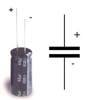
- Capacitors (0.1μF, 1μF)
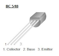
- Transistors (BC 548, BC 187)
- NE 555
- IC 7474
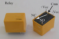
- 6V or 12V Relay (According to Vcc)
Working Procedure of Clap Switch Circuit
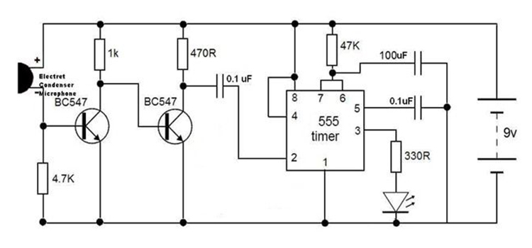
- Here, the 555 IC operates in Monostable Multivibrator mode. It can be triggered with a low voltage at 2nd pin.
- The collector voltage of BC 548 is connected to the trigger pin of 555.
- High amplitude sound signal in front of the condenser mic turns on the transistor BC 548.
- Then its collector voltage falls to low. Thus the 555 turns on for a time 1.1RC sec.
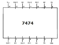
- Output of the 555 is connected to clock input of D-flip flop (IC 7474). It is a -ve edge triggered flip flop.
- When the monostable output goes to zero, the flop-flop’s output toggles.
The D-flip flop in the clap switch circuit works as follows
- Its output will be the input only after a clock pulse. Without clock, output will be the same; it will not affect the inputs.
- When Q’ is connected to D input, (say Q’=1) for the 1st clock pulse, Q=1 & Q’=0. for the next clock pulse Q=0 & Q’=1.
- That is (for time being considered, let flip-flop output is zero),for the 1st -ve transition output of the flip-flop goes to high. And for the next -ve edge, output will be low. It will continue for successive -ve edges
- In this way we can hold the output in low or high
- The flip flop out is connected to relay. When the output of flip flop is high it will energize the relay coil
- So the bulb connected on the relay will toggle with each clap or any sound
Datasheets for the switching circuit
Components Pinout

Conclusion
This circuit will work with 6V as well as 12V. So you can select transformer rating 230V-6V or 230V-12V. But be consistent with what you use throughout the project.
Subscribe to our newsletter
& plug into
the world of circuits