Digital Oscillators | Wein Bridge and Phase Shift
We all know that an oscillator is a circuit that produces periodic electric signals such as sine waves or square waves. The application of oscillators includes sine wave generators, local oscillators for synchronous receivers, etc.
You may find different types of oscillators all around with their own pros and cons. But if you can make your own digital oscillator, then you can customize it according to your preferences which can help you minimize the pros and maximize the cons of that circuit.
The classification of oscillators is based on their performance and the components used. Among them, the Wein bridge oscillator and Hartly Colpitts oscillator are pretty prominent.
In this article, we will discuss the making process of 3 different oscillator circuits which are –
- The wein bridge oscillator using the 741 op-amp IC which is a low-frequency oscillator.
- The RC phase shift oscillator using the BJT which is a transistor-based remote-control oscillator.
- The RC phase shift oscillator using the 741 op-amp IC which is a sinusoidal oscillator used to produce sustained well-shaped sine wave oscillations.
The good news is, you can make these circuits easily in your home at a low cost, and you can use them for different applications such as local oscillators for synchronous receivers, musical instruments, study purposes, etc.
So, why are we waiting? Let’s dive in below and learn how to build your own digital oscillators.
2. Wein Bridge Oscillator using ic 741 op amp
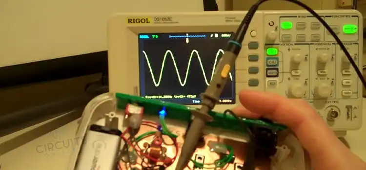
Here we’ll show you how you can make an audio frequency sine wave oscillator of high stability and simplicity named the Wien bridge oscillator. The op-amp that is used in this oscillator circuit works as the non-inverting amplifier. You don’t need to provide any phase shift to the feedback network for this circuit.
This circuit is simply a series RC network in one arm and a parallel RC network in the adjoining arm. Resistors Ri and Rf are connected in the remaining two arms.
Now, let’s see how we can build this circuit below.
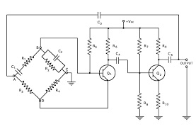
Wien Bridge Oscillator Circuit Diagram
Components Required
- Resistors (1KΩ, 1.5KΩ x2)
- Potentiometer(4.7KΩ)
- Capacitor(0.1µF x2)
- 741 Op amp
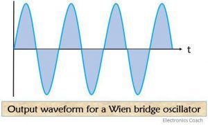
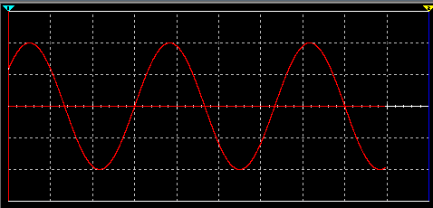
Output Waveform
Working of Wein bridge Oscillator
- The feedback signal in this oscillator circuit connects the non-inverting input terminal so that the op-amp works as a non-inverting amplifier.
- The condition of zero phase shift around the circuit is achieved by balancing the bridge, zero phase shift is essential for sustained oscillations.
- The frequency of oscillation is the resonant frequency of the balanced bridge and the expression is fo = 1/2πRC
- At resonant frequency ( ƒo), the inverting and non-inverting input voltages are equal and “in-phase” so that the negative feedback signal will cancell out by the positive feedback causing the circuit to oscillate.
- From the analysis of the circuit, it is clear that the feedback factor β= 1/3 at the frequency of oscillation. Therefore, for sustained oscillation, the amplifier must have a gain of 3 so that the loop gain becomes unity.
- For an inverting amplifier the gain is set by the feedback resistor network Rf and Ri and is given as the ratio -Rf/Ri.
The above tutorial for making a Wein Bridge Oscillator is quite simple, and we hope you won’t face any major problems while developing this project by following the instructions above.
2. RC Phase Shift Oscillator Using BJT | Transistor-Based RC Oscillator
The frequency-generating circuit of an oscillator circuit depends on the elements that are used in the circuit, and we have used the BJT in this RC phase shift oscillator. Let’s discuss how we can make this transistor-based RC oscillator below.
What Is An Oscillator
Before we jump into a transistor-based oscillator circuit or RC phase shift oscillator using a transistor, let’s define the oscillator itself. An oscillator is an electronic circuit that acts as a sine wave generator.
The only requirement of an oscillator is a DC power supply source. It is widely used in frequency variable signal generators. So it is a common basic electronic circuit.
A basic oscillator circuit contains the following parts –
- Amplifier
- Frequency selective network
- Positive feedback from output to input
Condition for Sustained Oscillations
The basics of an oscillator circuit must obey Barkhusen’s criteria to provide sustained oscillation, it states that
- Total loop gain of the circuit must be equal to unity. ie; Aß = 1. (Where A is the gain of the amplifier and ß is the loop gain or feedback factor.)
- Net phase shift (or total phase shift) around the circuit must be 0˚or 360˚.
Circuit Diagram of RC Phase Shift Oscillator Using BJT
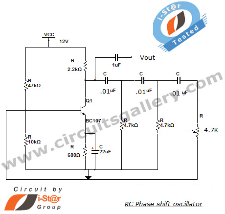
Components Required for Phase Shift Oscillator
- Resistors(47kΩ; 10kΩ; 2.2kΩ; 4.7kΩ x 2; 680Ω)
- Capacitors(22µF; 1µF; .01µFx3)
- Transistor BC107
- Potentiometer
Sustained Output Waveform of RC Phase Shift Oscillator
Working of Transistorized RC phase shift oscillator
- Here we are using a BC107 transistor for implementing RC phase shift oscillator. BC107 is an audio frequency transistor that is made up of silicon.
- If we use a common emitter amplifier with a resistive collector load, there will be a 180˚ phase shift between the voltages at the base and collector. It will also amplify the signal.
- The feedback circuit section must produce another 180˚ shift to meet the Barkheusan criterion.
- Three sections of phase shift networks are used which are constituted by resistive-capacitor combination. That each section introduces a 60˚ phase shift at the resonant frequency.
- The positive feedback from output to input will lead the circuit to operate as an oscillator.
- Phase shift oscillator is a particular type of audio frequency oscillator. The output signal is obtained across 1µF capacitor and ground terminal as shown in circuit schematic.
Design of RC Phase Shift Oscillator Using BJT
If all the resistors, R, and the capacitors, C in the phase shift network are equal in value, then the frequency of oscillations produced by the RC oscillator is given as:

Where ƒr is the Output Frequency in Hertz
R is the Resistance in Ohms
C is the Capacitance in Farads
N is the number of RC stages. (N = 3)
Why RC phase shift oscillator uses 3 RC stages
- The number of RC stages will improve the frequency permanence. The total phase shift established by the feedback network must be 180 degrees for sustained oscillations. If we are using the ‘N’ RC stages, each RC section provides a 180/N degree phase shift.
- When 2 RC sections are cascaded, the frequency stability is poor. For the 3 sections cascaded, the phase change rate is high so we get improved frequency stability. However, for 4 RC sections, there is a good phase change rate resulting in the most stable oscillator configuration. But 4 RC segments enhance cost and makes circuit complexity.
- Hence, phase shift oscillators make use of 3 RC sections, and in that each section gives a phase shift of 60 degrees. The latter 3 RC networks are generally used in high-precision applications where cost is not much considered and only accuracy plays a major role.
Apart from designing an RC phase shift oscillator using a transistor, you can implement it using op amp 741. Note that we have kept a 4.7k ohm potentiometer instead of a regular resistor here.
3. RC Phase Shift Oscillator Using 741 Op Amp | Design and Output Waveform Simulation
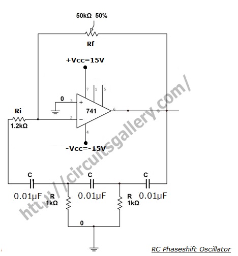
The main component you’re going to need for this RC phase shift oscillator is a 741 op-amp IC. Using a regenerative feedback RC filter network, you can use it as an inverting amplifier with its output fed back into its input. That’s why the name of this oscillator is RC phase shift oscillator.
You can change the frequency of this oscillator by customizing the capacitance of the capacitors. Here, the feedback network has a phase shift from zero to 270° at low and high frequencies respectively. Let’s learn more details about this circuit below.
Circuit Diagram of RC Phase Shift Oscillator Using 741
Components Required for RC Phase Shift Oscillator
- Resistors (1.2KΩ, 1KΩx2)
- Potentiometer (50KΩ)
- Capacitors (0.01µFx3)
- 741 Op Amp
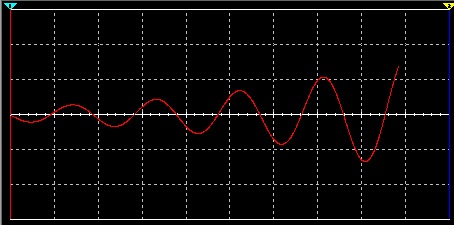
Transient Output Waveform
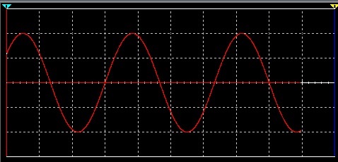
Sustained/Steady-State Output Waveform
Working Procedure of RC Phase Shift Oscillator Using 741
- The feedback network offers 180 degrees phase shift at the oscillation frequency, and the op-amp is configured as an Inverting amplifier it also provides 180 degrees phase shift. Hence, the total phase shift around the loop is 360=0 degrees, which is essential for sustained oscillations.
- At the oscillation frequency, each resistor-capacitor filter produces a phase shift of 60° so the whole filter circuit produces a phase shift of 180°.
- The energy storage capacity of the capacitor in his circuit produces a noise voltage that is similar to a small sine wave, it is then amplified using an op-amp inverting amplifier.
- By taking feedback, the output sine wave also attenuates 1/29 times while passing through the RC network, so the gain of the inverting amplifier should be 29 in order to keep the loop gain as unity.
- The unity loop gain and 360-degree phase shift are essential for sustained oscillation.
- RC Oscillators are stable and provide a well-shaped sine wave output with the frequency being proportional to 1/RC therefore, a more comprehensive frequency range is possible when using a variable capacitor.
- However, RC Oscillators are restricted to frequency applications because at high frequencies the reactance offered by the capacitor is very low, so it acts as a short circuit.
Why It Uses 3 Rc Stages
- A number of RC stages help improve frequency stability. The total phase shift introduced by the feedback network is 180 degrees, if we use N RC stages each RC section provides a 180/N degree phase shift.
- When 2 RC sections are cascaded, the frequency stability is low. For 3 sections cascaded the phase change rate is high so there is improved frequency stability. However for 4 RC sections there is an good phase change rate resulting in the most stable oscillator configuration. But 4 RC sections increases cost and makes circuit complexity.
- Hence phase shift oscillators make use of 3 RC sections in which each section provides a phase shift of 60 degree. The latter is generally used in high precision applications where cost is not much regarded and only accuracy plays a major role.
Designfrequency of Oscillation (F)
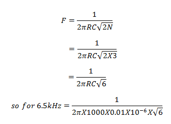
Gain of the Op Amp Inverting Amplifier (G)
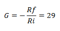
The attenuation offered by the feedback RC network is 1/29, so the gain of the inverting amplifier should be 29
Use Ri=1.2 KΩ
So, Rf=35KΩ
Use a 50KΩ potentiometer and adjust its value to obtain output on CRO
Components Pinout
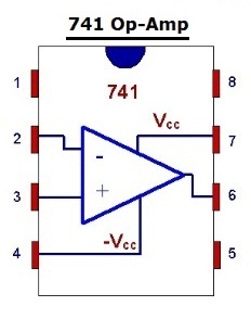
An op-amp can be in inverting and non-inverting modes. Here, the 741 op-amp IC keeps this RC phase shift oscillator in the inverting mode. Remember that the pin connections are vital while implementing this circuit.
Conclusion
Digital oscillators are one of the most common circuits in electronics projects. If you want to deal with different kinds of frequency waves, you can make a Wein bridge oscillator or an RC phase shift oscillator as instructed in the first section of this article. You can design the RC phase shift oscillator in two ways – using a transistor or an op-amp 741 IC. Both are described with demonstration above, and we hope, now you can make your own oscillator circuit by following those instructions. Thanks for reading and best wishes for your upcoming electronics project using this digital oscillation circuit.
Subscribe to our newsletter
& plug into
the world of circuits
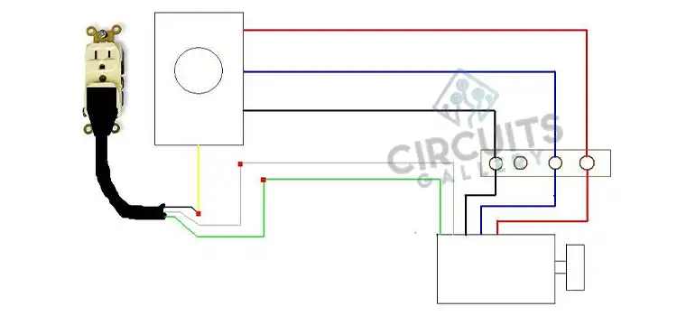
![Rotary Changeover Switch Wiring Diagram [Explained]](https://www.circuitsgallery.com/wp-content/uploads/2023/10/Rotary-Changeover-Switch-Wiring-Diagram.webp)
![[Easy Explanation] How to Convert 4 to 20MA to 0 to 5V](https://www.circuitsgallery.com/wp-content/uploads/2023/09/How-to-Convert-4-to-20MA-to-0-to-5V.webp)