3 Speed Fan Capacitor Wiring Diagram | A Step-by-Step Guide
Ceiling fans are common fixtures in many homes, providing comfort and air circulation. These fans operate using single-phase motors that require the use of capacitors for their proper functioning, especially when it comes to controlling fan speed.
This article provides a step-by-step guide to understanding the wiring diagram of a 3-speed fan capacitor, which is crucial for controlling the fan’s speed and ensuring proper functionality. It also explains the wiring of a 3-wire capacitor and the significance of different wire colors in fan switches.
Understanding the wiring of the capacitor and its connections is essential for anyone looking to install or troubleshoot ceiling fan systems. So, let’s begin.
Wiring Diagram of 3 Speed Fan Capacitor
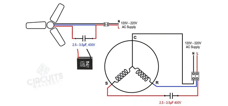
Below is a basic and simple figure of an external connection that links the ceiling fan, fan speed regulator, and ON/OFF switch to a single-phase power supply at home. The internal connection of the running coil/winding, starting coil/winding, and the capacitor is also shown.
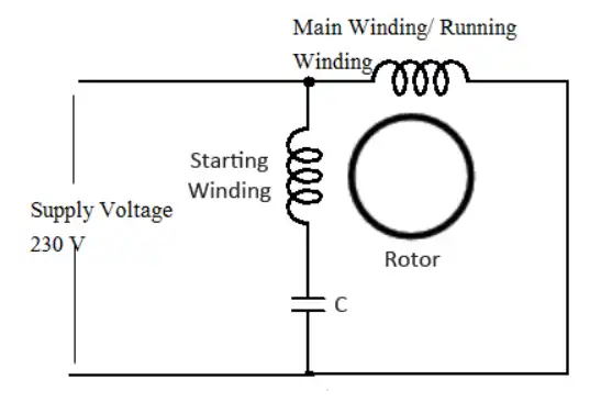
A motor requires two windings: one to run the motor and another to start the motor. The ceiling fan is powered by a single-phase induction motor that does not self-start. A single-phase AC motor requires two independent phases to produce a rotating MMF (Magnetomotive Force), which in turn rotates the rotor.
How Do You Wire a 3-Speed Fan Control?
Perform the following steps to wire a 3-speed fan controller:
- Turn off the power at the circuit breaker panel or fuse box.
- Install the controller in a regular single-gang wall box.
- Connect the wall box, power source, and fan units to be controlled via the conduit. Allow around 4 inches of wire in the box for connections as the following figure.
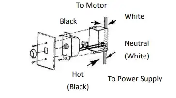
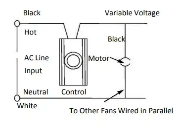
- Connect the wires as shown. Connect the black wire from the supply line to one of the controller’s black wires. Connect the controller’s second black wire to the fan motor’s black wire. Connect the supply line’s white wire to the fan motor’s white wire.
- Make sure the wire strands are straight and twist the control wire leads to the circuit wires together to attach them. Wrap a wire nut around each connector. The cover dent on the cover plate indicates the upward position.
- When using a solid state speed controller, the fan will make humming noise at a low speed. This hum does not affect the fan’s operation and is acceptable in most commercial/industrial settings.
How Do You Wire a 3 Wire Capacitor
Perform the following steps to wire a 3- wire capacitor:
- Remove the power supply cord from the electrical socket – in other words, ensure that all power to the device being repaired has been switched off.
- Remove the old starting relay while keeping the old overload protection.
- Connect the wire with a single pin terminal to the air conditioning compressor’s “start” terminal.
- Connect the other wire with the pin termination to the air conditioning compressor’s “run” terminal.
- Connect the old starting relay line to the spade terminal on the “run” wire (insulating sleeve).
- Restore power to the grid
Many systems will have these terminals designated so that the three leads on a start/run capacitor may be wired correctly: S stands for Start wire connector, R stands for Run wire connector, and C stands for Common connector.
What Color Wires Go to 3 Speed Fan Switch
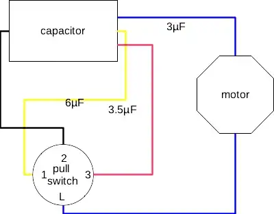
Black capacitor wire connects to a reverse switch at terminal 2. Blue capacitor wire (3µF, 350V) goes into the motor housing. Red capacitor wire (3.5µF, 200V) goes to switch terminal 3. Yellow capacitor wire (6µF, 200V) goes to switch terminal 1. The figure below illustrates the connection clearly:
How Do You Wire a Capacitor to a Fan
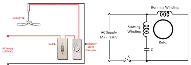
The ceiling fan has two windings, one that is running and one that is commencing. The capacitor must be connected in series with the starting winding and then across the power supply. The running winding, on the other hand, must be linked directly across the power supply.
You can see the connection of the ceiling fan with the regulator and switch in the figure below. Connect the switch in series first, then the regulator, and finally the ceiling fan.
Can I Use 3.5 Capacitor in Ceiling Fan
Using a 3.5 μF (microfarad) capacitor in a ceiling fan depends on the specific requirements of your ceiling fan’s motor and its design. The capacitor in a ceiling fan is typically used for speed control, and different fans may require capacitors with varying capacitance values to achieve different speeds.
If the original capacitor in your ceiling fan is damaged or you want to change the speed settings, it’s essential to use the correct replacement capacitor with the same or a similar capacitance value recommended by the fan’s manufacturer. Using a 3.5 μF capacitor in a ceiling fan designed for a different value may lead to undesirable speed or performance characteristics and could potentially damage the motor or the fan itself.
To ensure the safe and optimal operation of your ceiling fan, consult the manufacturer’s specifications, user manual, or customer support to determine the correct capacitor value and obtain a suitable replacement if necessary.
Frequently Asked Questions
How Does a 3-Speed Fan Work?
The first two wires of a three-speed fan are the fan’s power supply wires. The third wire is directly connected to the output of the built-in ‘Hall Sensor’ chip, which provides output pulses during fan spinning. A monitoring circuit can see the rotation with the help of this third wire.
Why do ceiling fans need a capacitor?
The switch housing inside a fan has a black box which is a capacitor. This is a key component of the fan that allows it to function properly. The capacitor is utilized to not only start but also spin the fan. Simply put, the capacitor generates a magnetic flux (torque) that causes the fan to rotate.
Final Thoughts
The wiring diagrams for 3-speed fan capacitors provide a clear roadmap for fan installation and control. The significance of different wire colors and capacitor values helps users make informed choices when dealing with these components. When it comes to capacitor replacement, it’s crucial to adhere to the manufacturer’s specifications to ensure that your ceiling fan operates efficiently and safely. By following these guidelines and principles, you can enjoy the benefits of a well-functioning ceiling fan in your living spaces.
Subscribe to our newsletter
& plug into
the world of circuits