How to Interface I2C External EEPROM 24LC64 to PIC Microcontroller
Microcontrollers are standalone chips since they have memory and processor embedded. The integrated memory of microcontrollers stores embedded code and other temporary variables for the execution of the program. CircuitsGallery published many microcontroller tutorials and PIC microcontroller projects.
Sometimes we may use non-volatile memories (i2c devices) with microcontrollers in case of storing permanent data. In this article, I am gonna explain how we interface an external memory i2c microchip with a PIC microcontroller. For that, I took Microchip’s 24LC64, which is a 64 Kbit Electrically Erasable PROM also called I2C. This i2c tutorial will definitely serve you while doing i2c projects.
The LCD module is used to display the data. The program progresses by writing data to the 24LC64 i2c memory chip then reading it and displaying it on the LCD screen.
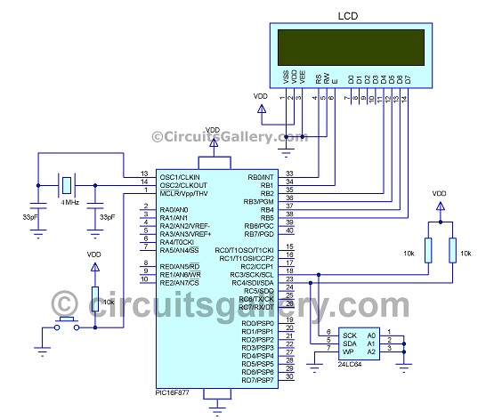
Schematics Diagram for Interfacing Microchip I2C EEPROM to PIC
Now let’s see the circuit diagram showing how to use i2c with PIC.
Components Required
- PIC 16F877 Microcontroller
- 24LC64 Memory chip
- LCD Module
- Capacitors (33pF x 2)
- Crystal Oscillator 4MHz
- Resistor 10kΩ
How I2C Interface Works with PIC
- 16×2 LCD is connected on PORTB of PIC which shows the read and writes operations to the viewer.
- Here two-wire interface (with SCL and SDA pins) is used for the communication between the Memory device and the PIC Microcontroller also called “I square C (I2C)” or “inter-integrated circuit”
- I2C has the advantage that can connect the different devices in the same connection with the help of device address and start and stop signals.
- In such interfacing, PIC acts as a master and I2C memory servers as slaves then master and slave communicate with each other. (There are situations where we use i2c master, but not here)
- SCL (Serial Clock Line) is the clock line. It is used to synchronize all data transfers over the I2C bus and SDA (Serial Data) is the data line.
- To start communication the channel should be ideal (which means it is not used by other devices and it is free), in an ideal stat both the pins SDA and SCL by applying a high signal.
The figure below shows the timing diagram for the SDA and SCL signals
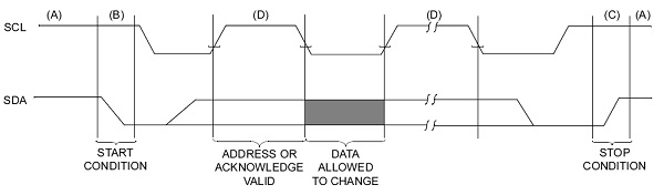
- Here at point (A) SCL and SDA are at HIGH which is called the ideal state, at point (B) SCL remains HIHG, and then SDA goes to LOW called the Start condition.
- After sending the start signal, send the device address with the control command (read or write) to the slave.
- The control command informs the slave that a read or writing operation is going to be performed.
- After sending the control command slave will send ACK to the master.
Write Operation
- After sending the start signal PIC will send the device address with a write command for the EEPROM chip (i2c chip) is “0xA0”.
- The next step is to send the registered address, which is the memory location where the data is to be written. (For low memory devices it can send by simple 8-bit).
- Here we are using 64Kb memory so we have to send the registered address twice (I used 0x0000), this may send the registered address by two 8 bits.
- After this send the data sequentially then send a stop signal.
Read Operation
- To read from a specified address first send the device address with the write command.
- Then send the registered address as two 8 bits.
- A restart signal is sent (Here start signal is sent without sending a stop signal called a restart signal).
- Then receive the data sequentially, The received data is stored on a buffer and is displayed on the screen.
Program for I2C External EEPROM interface
We had written PIC embedded program for this kind of memory interfacing. The compiler used is Hi tech C.
[cc lang=‘c’] #include

#include

/////////////////////////////LCD FUNCTIONS\\\\\\\\\\\\\\\\\\\\\\\\\\\\\\\\

#define RS RB0
#define EN RB1
#define D4 RB2
#define D5 RB3
#define D6 RB4
#define D7 RB5
#define _XTAL_FREQ 4000000
#define _CONFIG 0x3F32

void LCD_OUT(char a, char b, char *n);
void LCD_INIT();
void LCD_CHR(char m);
void LCD_DATA(char m);

void LCD_DATA(char m)
{
    if(m & 1)D4 = 1;
    else D4 = 0;

    if(m & 2)D5 = 1;
    else D5 = 0;

    if(m & 4)D6 = 1;
    else D6 = 0;

    if(m & 8)D7 = 1;
    else D7 = 0;
}

void LCD_CMD(char m)
{
    RS = 0;
    LCD_DATA(m);
    EN = 1;
    __delay_ms(4);
    EN = 0; }
    LCD_CLEAR() {
    LCD_CMD(0);
    LCD_CMD(1);
}

void LCD_OUT(char a, char b, char *n)
{
    char p,q,r;
    if(a == 1)
    {
        p = 0x80 + b;
        r = p>>4;
        q = (0x80+b) & 0x0F;
        LCD_CMD(r);
        LCD_CMD(q);
    }

    else if(a == 2)
    {
        p = 0xC0 + b;
        r = p>>4;
        q = (0xC0+b) & 0x0F;
        LCD_CMD(r);
        LCD_CMD(q);
    }

int i;
for(i=0;n[i]!=’\0′;i++)
LCD_CHR(n[i]);
}

void LCD_INIT()
{
    LCD_DATA(0x00);
    __delay_ms(20);

    LCD_CMD(0x03);
    __delay_ms(5);

    LCD_CMD(0x03);
    __delay_ms(11);

    LCD_CMD(0x03);
    LCD_CMD(0x02);
    LCD_CMD(0x02);
    LCD_CMD(0x08);
    LCD_CMD(0x00);
    LCD_CMD(0x0C);
    LCD_CMD(0x00);
    LCD_CMD(0x06);
}

void LCD_CHR(char m)
{
    char T1,T2;
    T1 = m&0x0F;
    T2 = m&0xF0;
    RS = 1;
    LCD_DATA(T2>>4);
    EN = 1;
    __delay_ms(5);
    EN = 0;
    LCD_DATA(T1);
    EN = 1;
    __delay_ms(5);
    EN = 0;
}

//////////////////////I2C Functions\\\\\\\\\\\\\\\\\\\\\\\\

void I2CInit();
void I2CStart();
void I2CStop();
void I2CRestart();
void I2CAck();
void I2CNak();
void I2CWait();
void I2CSend(unsigned char dat);
char I2CInitval[10];
char rcdata[30];
double rdaddr=0x00;
unsigned char I2CRead();
unsigned char I2CData[] = {“i-St@r”};
unsigned char i,j;

void I2CInit(void)
{
    TRISC3 = 1;
    TRISC4 = 1;
    SSPSTAT |= 0x80; // Slew rate disabled
    SSPCON = 0x28;
    SSPADD = 0x28; /* 100Khz @ 4Mhz Fosc */
}

void I2CStart()
{
    SEN = 1;
    while(SEN);
}

void I2CStop()
{
    PEN = 1;
    while(PEN);
}

void I2CRestart()
{
    RSEN = 1;
    while(RSEN);
}

void I2CAck()
{
    ACKDT = 0;
    ACKEN = 1;
    while(ACKEN);
}

void I2CNak()
{
    ACKDT = 1;
    ACKEN = 1;
    while(ACKEN);
}

void I2CWait()
{
    while ((SSPCON2 & 0x1F ) || ( SSPSTAT & 0x04 ) );
}

void I2CSend(unsigned char dat)
{
    SSPBUF = dat;
    while(BF);
    I2CWait();
}

unsigned char I2CRead()
{
    unsigned char temp;
    RCEN = 1;
    while(!BF);
    temp = SSPBUF;
    I2CWait();
    return temp;
}

//////////////////MAIN FUNCTION\\\\\\\\\\\\\\\\\\\\\\\\\\\\

void main()
{
    int i;
    TRISB = 0x00; // Set PORTB as Output
    LCD_INIT(); // Initilise LCD
    LCD_CLEAR(); // Clear LCD
    LCD_OUT(1,1,”WRITE:”);//Print “WRITE” on LCD 1st row 1st colum
    LCD_OUT(2,1,”READ :”);//Print “READ” on LCD 2nd row 1st colum
    LCD_OUT(1,7,I2CData);

////////////////EEPROM READ and WRITE\\\\\\\\\\\\\\\\

    I2CInit();
    I2CStart();
    I2CSend(0xA0);
    I2CSend(0x00);
    I2CSend(0x00);

    for(j=0;j<6;j++)
    {
        I2CSend(I2CData[j]);
    }

    I2CStop(); __delay_ms(100); I2CStart(); I2CSend(0xA0); I2CSend(0x00); I2CSend(0x00); I2CRestart(); I2CSend(0xA1);

    for(j=0;j<6;j++)
    {
        rcdata[j]= I2CRead();
        I2CAck();
    }
    if (i - 1)
        I2CAck();
    else
        I2CNak();

    I2CStop();
    LCD_OUT(2,7,rcdata);

    while(1);
}
[/cc]
What is Next
To upload this embedded program you need PIC Programmer, as we know most of the new generation Laptops come without RS232 Serial Interface. You may visit circuitsgallery on a continuous basis to get new circuits, microcontroller tutorials, and projects.
Subscribe to our newsletter
& plug into
the world of circuits
