How is an Ammeter Connected to a Circuit
To measure the current of something, an ammeter is connected in parallel with it in the circuit. When we attach the ammeter to the circuit, it measures the current of a component without alternating or participating in the circuit.
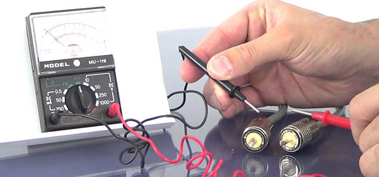
You should visually examine your ammeter before taking measurements with it. Inspect the meter, test probes, and accessories for physical damage. Check that all plugs are properly fastened, and keep a lookout for any exposed metal or fractures in the case.
How is an Ammeter Connected to a Circuit
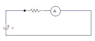
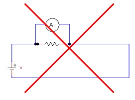
An ammeter is always connected in series with the circuit whose current you want to measure. An ammeter, like a charge tollbooth, counts the charges that pass by, and, like a tollbooth, it must be placed directly in the middle of the road. As a result, you would connect an ammeter as the figure 1, never like figure 2.
Why Ammeter is Connected in Series
An ammeter is a device that measures the amount of current that flows across a circuit. It has an extremely low resistance (near zero). If it is linked in parallel, it will draw the majority of the current and will be harmed. As a result, it is linked in series.
If the Ammeter is Connected in Parallel
Because the ammeter’s resistance is so low, a considerable quantity of current flows through it when it is linked in parallel. As a result, connecting this device in parallel causes it to burn out.
Frequently Asked Questions
Why is an ammeter a low resistance device?
Ammeters are used to measure the intensity of current in an electric circuit. Because they are constantly attached in series with a circuit, their introduction should not affect the current, resulting in low resistance.
Conclusion
If you have a multimeter instead of an ammeter, you also have to connect it in parallel to measure current. More importantly, if you are measuring alternate currents, make sure you have an expert to look after the experiment.
Subscribe to our newsletter
& plug into
the world of circuits