Engineering Projects Using GPS Module | Microcontroller, Speedometer, and USB Interface
You may already know that the GPS (Global Positioning System) navigation device precisely computes geographical location by receiving the necessary information from GPS satellites which is completely free, and it doesn’t cost any kind of subscription fee to its users. Maybe that’s the reason why it is being used massively. It is also popular in vehicles and other navigation equipment.
But do you know what is a GPS receiver? The GPS receiver is an electronic device capable of receiving GPS signals to decide the device’s location on Earth. Now, what if we tell you that you can make your own GPS receiver so that you can explore GPS systems as you like? Sounds interesting right? Well in this article, we are going to show you how you can make an interface GPS receiver with an 8051 microcontroller circuit.
Again, the GPS speed meter provides the location, speed, or other information of moving objects such as vehicles, running men, flying helicopters, aircraft, boats, or ships based on GPS coordinates. We also have demonstrated how you can make a GPS speed meter so that you can monitor much more information like speed, time, position, satellite in use, no of satellite, satellite ID number, and SNR (Signal to Noise ratio)!
Finally, as most communication-related engineering projects are based on the GPS module, we’re also going to show you how to configure the GPS modules to get desired output in this article.
So, if you are interested in engineering projects using GPS modules, then this article is just for you. Let’s explore below.
Interfacing GPS Receiver with 8051 Microcontroller AT89C52
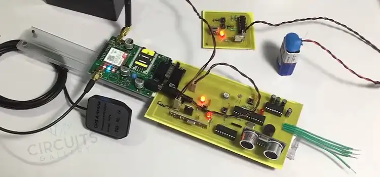
The GPS interfacing with microcontrollers embedded design by interactive simulation tutorial will be a stepping stone to GPS interface engineering project kits. For this Interfacing GPS Receiver, you’ll only need a GPS interfacing with microcontrollers and LCD (16×2). The LCD is used to display the latitude and longitude, continually updating the GPS data.
You can use the KEIL compiler to program 89C51 in Embedded C. UART in 89C51 can be used here to connect GPS with Microcontroller. Let’s explore more about this GPS receiver below.
What is GPS
Just before going to an interfacing GPS receiver with the 8051 programs, it is better to know what is GPS. GPS stands for Global Positioning System (GPS), which is a satellite-established navigation scheme built with a network of 24 satellites + 3 backup satellites positioned into orbit by the U.S. Department of Defense.
In the beginning stage, GPS was aimed at military operations only. Though in the 1980s, the U.S. government resolved to permit the GPS program to be used by common people like us.
Climate situations do not disturb the capability of GPS signals. GPS system works 24/7 everywhere on the Earth. There are no subscription fees or setup charges to use GPS.

[Image credit: http://en.wikipedia.org/wiki/GPS_(satellite)]
So let’s go-to interfacing GPS to microcontrollers.
Circuit Diagram for Interfacing GSM Module to 89C51 Microcontroller
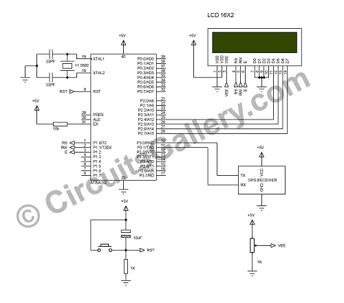
The figure below shows the schematics of how to interface GPS with microcontroller 8051 actually AT89C52.
Components Required for Interfacing GSM receiver to 89C51
- AT89C52
- Crystal (11.059MHz)
- Capacitor (33PF, 10µF)
- Resistor (10KΩ, 1KΩ)
- POT (10KΩ)
- LCD (16×2)
- GPS receiver
How To Interface GPS with 8051 Microcontroller (At89c52)
- The core component is the 89C51 microcontroller which drives the LCD module to display data obtained from the GPS receiver.
- GPS receivers frequently send information containing a number of data such as Global Positioning System fixed data (GGA), Geographic position-latitude/longitude(GLL), GNSS DOP and active satellites(GSA), GNSS satellites in view(GSV), Recommended minimum specific GNSS data(RMC), Course over ground and ground speed(VTG), Date and Time (ZDA), Datum reference (DTM).
- The GPS data start with “$GPXXX” where XXX is three letter identifier (GGA, GSA, etc.).
- I select GGA to extract the latitude and longitude, which can receive as $GPGGA, 153852.000, 1059.8656, N, 07558.2220, E, 1, 6, 1.19, 76.0, M,-92.4, M,,*45
- Here first we have to detect the ‘$’ sign, which indicates starting of GPS data, followed by ‘GP’ which is common for all data.
- The next aim is to catch up with the 3 letter identifier (GGA). Once you have successfully got the identifier ‘GGA’ then display the received data on LCD.
- To do this I made an infinite loop that compares all the received data with ‘$’ if this condition satisfies then check the next condition.
- The next condition is to check G, P, G, G, A if it also satisfies then skips one data to remove a ‘,’ (comma) since the format is $$GPGGA, 153852.000 …………
- Then wait for receiving the next comma for that another infinite loop is used which will break only when a comma is received.
- If a comma is found then the next data is latitude and longitude so we should store these data, I used two buffers variables of size12, lat[12] and lng[12]
- It stores the longitude and latitude, then displays ‘lat’ variable as “LAT:” and ‘lng’ variable as “LNG:” on the LCD screen.
You may possibly include the remaining GPS data by simply modifying the program.
NB: – The baud rate we selected to receive the GPS data we used is 4800.
We have demonstrated the interface GPS receiver with 8051 microcontroller AT89C52 below this section, and you can modify the program of interfacing the GPS receiver with 8051 in the future to get mode data from the GPS receiver. You can also use this as a GPS interface engineering project example.
Simple Digital GPS Speedometer Using PIC16F877A with LCD Display
A speedometer is a speed-measuring gauge used to calculate the speed of motor vehicles. There are mainly two types of speedometers – electronics and mechanical. A digital speedometer measures the speed and mileage of vehicles.
Normally both types work on the principle of electromagnetism, however, they have a disadvantage in that they cannot be used if there are no wheels on the moving object.
In this section, we are introducing a simple digital GPS speedometer using PIC16F877A with an LCD which is used for monitoring the speed or any other information. The NMEA message from GPS gives the necessary information since NMEA sends a line of data based on the GPS coordinates. Let’s learn the detailed mechanism of this digital GPS speedometer below.
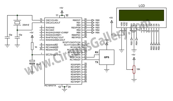
Circuit Diagram for Gps Speedometer Using Pic 16f877a Microcontroller
Components Required
- PIC16F877A
- GPS Module
- LCD 2×16
- Crystal (20MHz)
- Capacitor (22PFx2, 10uF)
- Resistor (1K)
- POT (10K)
- 5V Supply
- 12V supply
Working of Simple Digital Speedometer Using Pic 16f877a
- As seen in the circuit diagram, our small GPS digital speedometer requires both 5 V and 12 V power supplies. This is because the GPS module needs 12 V and other components require 5 V only. We can generate both these voltages from a single power supply circuit, so 12 V is enough for doing the GPS speed meter project with PIC 16F877A.
- When power is supplied, GPS is turned ON and gets started to work.
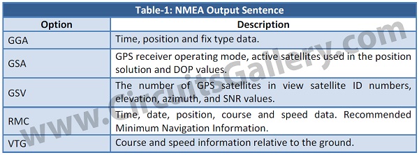
- GPS module continuously gives NMEA sentences based on the GPS coordinates. NMEA sentences from the GPS signal include time, position, GPS receiver operating mode, active satellites used, number of GPS satellites in view, satellite ID number, SNR (signal-to-noise ratio) values, azimuth values, elevation, position, date, time and speed of the GPS system with speedometer.
- Every NMEA lines start with a dollar symbol ‘$’ which indicates starting of sentences. Every first sentence of GPS information will contain $GPGGA, which indicates global positioning system fixed values for the GPS system.
- The information content for each NMEA sentence is shown in the table given below.
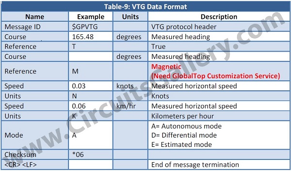
- The given table below describes the values in the VTG sentence from the GPS system.
- In the GPS module by default, you will not get $GPVTG, you have to enable it by using SiRFDemo software. If you want to know how to enable VTG value, Insha Allah we will try to publish an article on that in the future.
- After enabling the VTG sentence, the GPS system will start giving values continuously. To get the optimum values for the GPS module we have to filter these sentence values.
- We only need the sentence starting with $GPVTG here, so I have filtered sentences starting with $GPVTG from the GPS module.
- I have used PIC 16F877A for receiving the filtered values and LCD2x16 for displaying the values.
- An infinite loop that continuously checks for receiving ‘$’ is programmed on the coding side. After receiving the data correctly, the controller then checks for the order ‘G’, ‘P’, ‘V’, ‘T’, and ‘G’ respectively.
- Each character is separated by commas in coding as shown above. A ‘for loop’ is programmed for generating 7 commas continuously (‘;’;) so the controller waits to receive it.
- After the 7 commas, an infinite loop is used to get the speed in km/hr unit. After collecting the sentences it is stored in a buffer and an LCD display is used for displaying the results.
These are the techniques I have used in designing this simple digital speedometer using PIC 16F877A.
A brief idea about how to make a digital GPS speedometer using PIC16F877A is demonstrated in this section This can prove an important project especially if you are making an RC helicopter, car, or drone system to measure its real-time speed.
GPS Module Configuration Using USB Interface and SiRFDemo
All GPS modems need to be connected to a computer system including a laptop or desktop or similar to that to verify their output. As the connector specifications are different for different devices, you can make the connections through serial or USB ports and also via Bluetooth. To make it easier for you, we are going to give you a brief explanation of how to configure the GPS modules to get desired output in this section below.
Components Required for Configuration of GPS
- GPS Module
- USB to Serial Converter (If PC has no serial port)
Steps for GPS Module Configuration With USB Interface
- For the configuration of GPS, the first step is downloading and installing the GPS configuration software. Here I have preferred the SiRFDemo software. Before installation please ensure that your system has the basic requirements needed.
- Also, ensure that USB to serial converter driver software has been installed on your system, and then find the COM port from the Device Manager in the control panel.
- Now connect the GPS module to your system using USB serial converter.
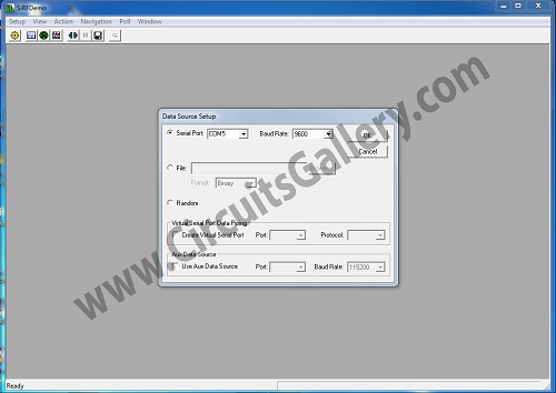
- Then open SiRFDemo software and define the COM port and Baud rate as 9600, and then click on the OK button.
- Then open Data source in the Action menu, before that please ensure that the GPS antenna is placed in the open space and not inside the building.
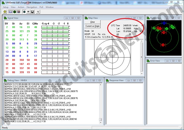
- Then you can see latitude and longitude values on the window as shown in the snapshot above.
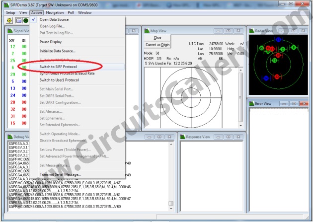
- Now click on ‘Switch to SiRF Protocol’ in the Action menu as shown below.
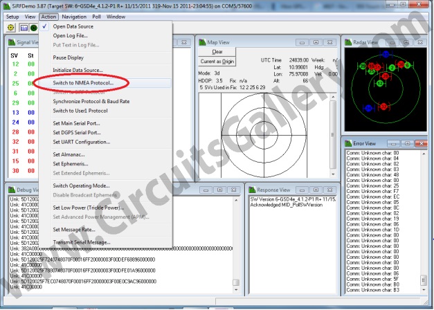
- Then click ‘Switch to NMEA Protocol’ in the Action menu as shown in the figure below.
- Now enable or disable the required NMEA sentences on’ NMEA Setup’ and then click on Send button.
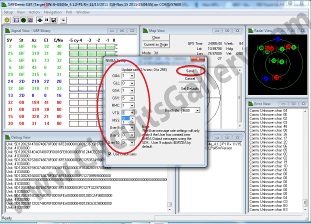
- Now your GPS module is restarted with configured values.
- You can also enable VTG using this command “$PSRF103,05,00,01,01*20″.
Now, we hope you have seen how easier it is to configure the GPS modem with your computer.
Conclusion
In this article, we have discussed the program of interfacing the GPS receiver with 8051, the system configuration of GPS using SiRFDemo software, and a brief idea about how to make a digital GPS speedometer using PIC16F877A. So, we hope now you understand how easily you can make a GPS receiver by following the given methods.
Especially, if you are working on a GPS interface engineering project, then this article will help you a lot in your project report. Moreover, you can make your own GPS devices and configure them according to your own preferences.
Subscribe to our newsletter
& plug into
the world of circuits
![How to Run a 12V DC Motor on 120V AC [Step-by-Step Guide]](https://www.circuitsgallery.com/wp-content/uploads/2023/10/How-to-Run-a-12V-DC-Motor-on-120V-AC.webp)
