Brown and Blue Wire Which is Positive? | Let’s Find Out
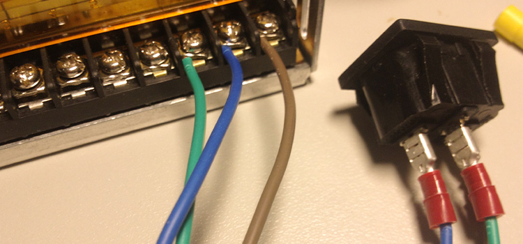
Between these two wires of interest, the brown wire, or the “hot wire” is the positive wire. It delivers power to the appliance and connects to the building’s black wire. On the contrary, the blue wire is the negative one and it actually takes power away from the appliance.
The brown wire and the blue wire, are both globally common wires and completely opposite in nature. Therefore, diving into the electrical work without basic knowledge of what these wires do can be hazardous.
What are the Differences Between Brown and Blue Wire?
When it comes to wiring, brown, blue, and green wires are common around the world. Whereas, black, white, and green are more common in the USA. The good news is that matching the wires with a fixture with international standards is still pretty easy.
Brown Wire
The Brown wire is called the “hot wire” and it is supposed to be connected to the building’s black wire. It is the active wire that typically has high potential. This wire is also known as the “live wire”, which means it transfers electricity to the appliance.
In other words, the brown wire is the positive wire. In general, the brown wire goes to the live terminal which is connected to the fuse.
Blue Wire
On the other hand, the blue wire is referred to as the “neutral wire” or “low potential” wire. It is the negative or “return” wire which will connect to the white wire. As for its function, it is to transfer electricity away from the appliance, as opposed to the brown wire.
The blue wire connects to the neutral terminal which is usually on the left of the plug. The combination of these two wires creates a circuit.
Standard Wire Color Code Table
Here’s a table that shows the standard wire color codes for AC power circuit wiring in the USA, UK, and Canada, including both the common colors and any alternative colors where applicable:
| Country | Function | Label | Color (Common) | Color (Alternative) |
| USA | Protective Ground | PG | Bare, Green, Green-Yellow | Green |
| USA | Neutral | N | White | Grey |
| USA | Line, Single Phase | L | Black or Red (2nd Hot) | |
| USA | Line, 3-Phase | L1 | Black | Brown |
| USA | Line, 3-Phase | L2 | Red | Orange |
| USA | Line, 3-Phase | L3 | Blue | Yellow |
| UK | Protective Earth | PG | Green-Yellow | Green-Yellow |
| UK | Neutral | N | Blue | Black |
| UK | Line, Single Phase | L | Brown | Red |
| UK | Line, 3-Phase | L1 | Brown | Red |
| UK | Line, 3-Phase | L2 | Black | Yellow |
| UK | Line, 3-Phase | L3 | Grey | Blue |
| Canada | Protective Ground | PG | Green or Green-Yellow | Green |
| Canada | Neutral | N | White | |
| Canada | Line, Single Phase | L | Black or Red (2nd Hot) | |
| Canada | Line, 3-Phase | L1 | Red | |
| Canada | Line, 3-Phase | L2 | Black | |
| Canada | Line, 3-Phase | L3 | Blue |
Uses of Brown and Blue Wire
The uses of brown and blue wires can vary depending on the electrical code and the specific country or region in which they are used. Below are common uses for brown and blue wires in electrical wiring in different contexts, according to electrician Alexander Ballesteros:
UK Electrical Wiring:
US Electrical Wiring:
Canadian Electrical Wiring:
Queries and Solutions
1. Is brown positive or negative?
The color brown, on its own, does not denote positive or negative in electrical wiring. The function of a wire is determined by its role in the circuit (e.g., live/phase, neutral, ground) and the specific wiring standards of the country or region.
2. Which wire is positive?
The concept of positive and negative wires is more commonly associated with direct current (DC) circuits, such as batteries. In DC circuits, red wires are often used to represent positive, while black or blue wires may represent negative. In alternating current (AC) circuits, the terms “positive” and “negative” are typically not used for power conductors.
3. Is blue or brown active?
The color blue or brown, in electrical wiring, can represent active conductors (live or phase) depending on the wiring standards of the country or region. For example, in the United Kingdom, brown is used for the live/phase conductor, while in the United States and Canada, the color coding is different. However, which one is considered “active” depends on the specific electrical code in use.
Final Thoughts
Regarding electrical works, you would hate to call an electrician every time for simple tasks such as installing a fixture, small issues with the ceiling fans, air conditioner, etc. For this reason, having the basic knowledge of some common color coding of the wires is a necessity. While being self-sufficient is good, you must remember that safety has to be the priority in your activities.
Subscribe to our newsletter
& plug into
the world of circuits