Getting Voltage but No Amps | Reasons & Solutions
Simply said, it signifies that your circuit is incomplete or defective. The causes of this problem are using the incorrect voltage, making the incorrect connection, and having problems with the panels or solar charge controller. To resolve the issue of getting voltage but no amps check for open circuits.
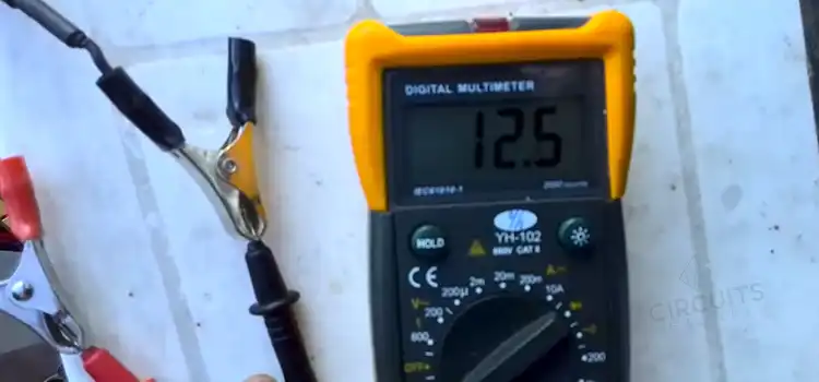
Another reason for zero amps could be incorrect measurement techniques, such as connecting a multimeter in parallel and blowing its fuse. Verify correct connections, measure resistance, test components, and ensure power supply compatibility to solve this problem.
What Causes Voltage but No Current
Several factors can cause voltage but no current. Possible causes are:
1. Open Circuit
- Cause: A break or disconnection in the circuit.
- Solution: Check for loose or disconnected wires, damaged components, or switches that are not closed. Repair or replace any faulty elements to complete the circuit.
2. Faulty Components
- Cause: Defective switches, blown fuses, or malfunctioning devices.
- Solution: Inspect and test each component individually. Replace any faulty components to restore the flow of current.
3. Insufficient Power Supply
- Cause: The power source does not provide enough current to operate the circuit.
- Solution: Verify that the power supply meets the current requirements of the circuit. Ensure the voltage output is stable and matches the circuit specifications.
4. Incorrect Connections
- Cause: Improperly connected components or reversed polarity.
- Solution: Double-check the wiring and connections to ensure they are correct and properly aligned. Verify the polarity of components and correct any incorrect connections.
5. Measurement Error
- Cause: Incorrect measurement techniques or equipment.
- Solution: Double-check the measurement setup and equipment. Ensure the ammeter is connected in series correctly. Calibrate or replace any faulty measurement equipment.
Is It Possible for a Faulty Switch to Cause Voltage Without Any Current Flow?
No, a faulty switch is unlikely to cause voltage without any current flow. A switch, when closed, allows the current to flow through the circuit. And when open, it interrupts the flow. If the switch is faulty and remains open, it would prevent both voltage and current from reaching the circuit.
Conclusion
High resistance can also stop the current to flow. If you suspect high resistance in a circuit, check for loose or corroded connections, damaged wires or components, improper wire gauges, or excessive length. Measure resistance at different points, inspect components for damage and ensure proper wire sizing to solve this.
Subscribe to our newsletter
& plug into
the world of circuits