How to Connect an Oscilloscope to a Circuit
Oscilloscopes are an important tool in any electrical engineer’s lab. A specific and exact guideline is maintained to connect an oscilloscope to a circuit. In particular, proper grounding is very vital for your safety as well as the safety of the integrated circuits (ICs) you’re testing. Setting oscilloscope controls, calibrating the oscilloscope, connecting oscilloscope probes, and compensating the probes are also correctly maintained, along with basic oscilloscope measurement techniques.
Can I Connect the Oscilloscope Anywhere in the Circuit
Yes, the oscilloscope probe is attached to an input channel with high internal resistance, and a multiplexer allows you to connect the probe to any point in your circuit. You can start at any point in the circuit and work your way to the beginning or end of the chain as long as the current is in a closed loop.
However, connecting your oscilloscope to any part of the circuit is not suggested. This can harm your oscilloscope and circuit, resulting in erroneous readings on your oscilloscope.
How to Connect an Oscilloscope to a Circuit
An oscilloscope’s primary function is to plot an electrical signal as it changes over time. Most scopes display a two-dimensional graph with time on the x-axis and voltage on the y-axis.
So to connect the oscilloscope, first need to connect the ground clip of the scope probe to the circuit’s ground plain or connector, and the probe tip to the circuit’s signal output. When these connections are completed, a line will appear on the oscilloscope’s screen, which is known as the signal waveform.
How Oscilloscope Is Used | Step by Step
There are a few steps to using an oscilloscope with a circuit, and they vary depending on the type of signal you’re looking at. The steps are mentioned below:
Setting up the Device
You need to properly ground the device when setting it up. It is required whenever the gadget is to be connected to a circuit.
Grounding the Oscilloscope
Grounding oscilloscope means connecting the oscilloscope to an electrical neutral point, such as the earth’s ground. The oscilloscope, for example, should be grounded by inserting its power cord into an outlet that is grounded to the earth’s ground.
Set up the Device Control
Steps to follow to set up the controls:
- Set the oscilloscope to display channel 1.
- Set the vertical volts/division scale and position controls to mid-range positions.
- Turn off the variable volts/division.
- Turn off all magnification settings.
- Set the channel 1 input coupling to DC.
- Initiate the device trigger to auto
- Turn the trigger of the device to channel one
- Set the device’s brightness control to a comfortable viewing level.
- Set the horizontal time/division and position controls to mid-range positions.
- Adjust the channel to achieve the desired result
Instrument Calibration
Appropriate instrument calibration is critical, especially if the ambient temperature has altered since you last used the device. It’s referred to as signal path compensation in the device, and you can learn more about it in the equipment’s handbook.
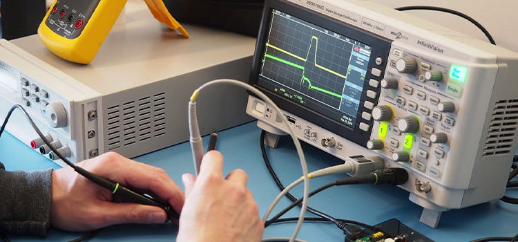
Connecting the Probes
After you’ve completed all of the preceding steps, you can connect the probe to the device. A probe will always assist you in gaining access to the device’s power/performance and then ensuring that the signal’s integrity is protected.
Measuring a signal requires two connections:
- The probe tip connection
- The ground connection
For grounding the probe to the circuit, most probes come with an alligator clip device. As a result, the grounding point should be connected to the circuit’s ground.
Compensating the Probe
Steps to follow-
- Connect the vertical channel to the probe.
- Continue by connecting the probe’s tip to the probe itself.
- Connect the probe’s ground clip to the ground.
- View the signal wave on the display screen
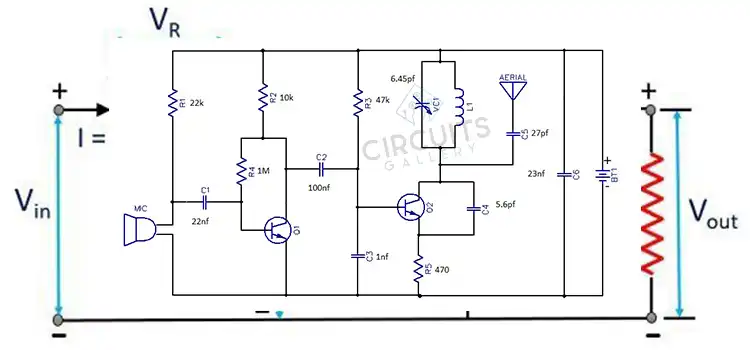
How Do I Connect a Power Supply to an Oscilloscope
The connection of a power supply to an oscilloscope is just done by connecting the higher potential portion of any properly regulated power supply to the positive terminal of the input probe of the oscilloscope which is large in size than the negative terminal. Similarly, connect the lower potential to the negative terminal of the input probe.
How Do You Use an Oscilloscope on a Breadboard
An oscilloscope is connected to a breadboard through BNC (coaxial cables) and CRO (cathode-ray oscilloscope). BNC to crocodile clip cables and single-strand jumper wires link the function generators and CRO to the breadboard.
For this first need to ensure that the power supply, function generator, and CRO grounds are all connected.
Conclusion
Connecting an oscilloscope to a circuit is a problem that many people have problems with. But with appropriate guidelines, it is way easier to connect an oscilloscope to a circuit and also to operate as required. So, the processes mentioned above should be followed to make a connection.
Subscribe to our newsletter
& plug into
the world of circuits
![What Gauge Wire for Trailer Brakes [Explained with Mathematical Reference]](https://www.circuitsgallery.com/wp-content/uploads/2023/06/What-Gauge-Wire-for-Trailer-Brakes.webp)
![Can A Bad Breaker Cause Low Voltage [Answered]](https://www.circuitsgallery.com/wp-content/uploads/2023/09/Can-A-Bad-Breaker-Cause-Low-Voltage.webp)