What Size Wire for 100 Amp Breaker | Appropriate Wire Size for a 100 Amp Circuit Breaker
According to NEC, the appropriate wire size for a 100 amp breaker without considering the material is 1 AWG. Whereas, a 100 amp branch circuit would require #3 AWG copper or #1 AWG aluminum wire.
For the homeowners, it is pretty common to get stuck on the issue of wire size for their electrical panel. The thumb rule is that the thicker the wire, the more amperage a wire can deliver. Using the correct wire size saves you and your appliances from electrical fire hazards.
What Size Wire for 100 Amp Breaker
The wire size used for a 100 amp main breaker depends on several factors. They include the length of the run, the type of conduit, ambient temperature, and the type of wire.
NEC Code
In the US, “AWG” or “American Wire Gauge” is the standard for measuring wire sizes. The correct wire size for a 100 amp breaker is 1 AWG. However, it is valid only if you do not consider the material.
It is a common mistake of the homeowners to choose smaller wire sizes such as #4 AWG and #2 AWG for 100 amp breakers and fry their sub-panel. The National Electrical Code provides an 80% requirement which acts as a key factor to determine the wire size.
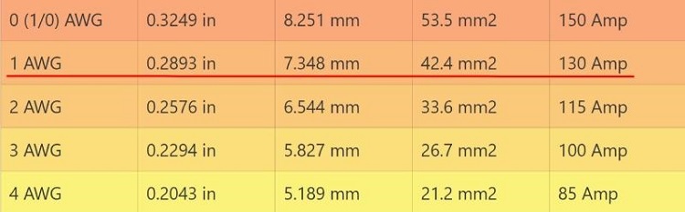
From the wire gauge chart, we see that a #3 AWG wire seems to be the most plausible wire size with 100-ampacity. However, the most appropriate one here is the #1 AWG wire with a 130 amp median capacity.
The 80% rule of NEC says that the maximum loading for any branch circuit is 80% of the rating of the circuit for ampacity of wire for any load. It is a safety measure that tells you about the actual ampacity.
Therefore, #1 AWG has 130A ampacity which conducts at most 104 amps. The #3 AWG wire has 100A ampacity but it is supposed to be used in circuits requiring 80 amps or less.
Considering the Material
If you consider the material, then the recommended gauge is 1 made of aluminum and 3 made of copper for a 100 amp branch circuit. It applies regardless of whether it is a breaker or subpanel.’
Copper vs Aluminum
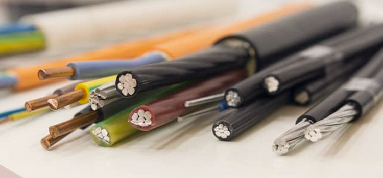
Once you have figured out the wire size required, the next problem is choosing the wire material. Aluminum wires are widely used because they are inexpensive, light, and flexible.
However, due to lower conductivity compared to copper, aluminum wiring needs a larger-sized wire. Another drawback is the antioxidant coating required to resist corrosion, unlike the copper-clad aluminum.
On the other hand, copper has better conductivity and can handle higher electrical loads. It also uses less insulation and has a lower wire gauge compared to aluminum. The heat-resistant and corrosion-resistant properties make it the most preferred wire material.
Choosing the Appropriate Size
When choosing between two gauge sizes for a 100 amp main breaker, you should know that bigger is always better. Opting to err on the side of caution is the best idea here.
Using the larger gauge will require you to spend more. However, if you choose too small a gauge, the circuits will go bad and as a result, the risk of electrical fire will go up.
Conclusion
Choosing the appropriate wire size for your 100 amp breaker is not as complicated as it seems. Always make sure to shut off the power higher up the line when working on a service panel. If you are unsure, seek the help of a licensed electrician.
Subscribe to our newsletter
& plug into
the world of circuits
![12V DC vs 12V AC [Key Differences]](https://www.circuitsgallery.com/wp-content/uploads/2023/12/12V-DC-vs-12V-AC.webp)
![What Are The 3 Wires On A Microwave Transformer [Answered]](https://www.circuitsgallery.com/wp-content/uploads/2023/11/What-Are-The-3-Wires-On-A-Microwave-Transformer.webp)