Can I Use 12 Gauge Wire on a 30 Amp Circuit? [Technically Answered]
No, a 12-gauge wire cannot be used on a 30-amp circuit. The maximum current a wire may safely carry is determined by its ampacity, which correlates with the wire’s gauge. You would be using a wire that is too small for the current it needs to carry if you use a 12-gauge wire for a circuit rated for 30 amps.
Based on the ampacity specifications needed for various circuits, the National Electrical Code (NEC) offers recommendations for wire sizing. Use a minimum of 10-gauge wire for a 30-amp circuit.
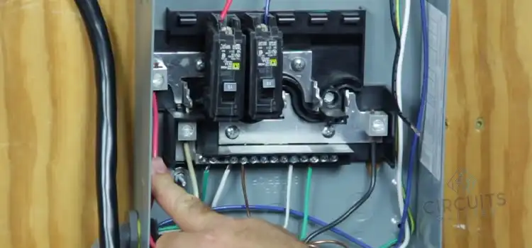
Is 12 Gauge Wire Good for 30 Amps?
A 12-gauge wire is not suitable for 30 amps. Here’s a table of wire gauges and their corresponding ampacity ratings according to the NEC.
| Wire Gauge Size | Ampacity Ratings (Maximum) |
| 14 AWG | 15 amps |
| 12 AWG | 20 amps |
| 10 AWG | 30 amps |
| 8 AWG | 40 amps |
So, for a 30 amps circuit, 10 gauge is appropriate. If we use an inappropriate wire gauge, the voltage drop across the wire can cause potential hazards. Let’s take an example.
The resistance of a wire can be calculated using the formula R = (ρ * L) / A, where ρ is the resistivity of the material (in this case, copper), L is the length of the wire, and A is the cross-sectional area of the wire.
For simplicity, let’s assume a 100-foot or 30.48 meters length of wire, cross-sectional area (A) of 12-gauge wire 3.31 mm² or 0.005128 square inches (approximate value), and resistivity (ρ) of copper 1.7 x 10^(-8) ohm-meter. The resistance of the 12-gauge wire,
R = (ρ * L) / A
R = (1.7 x 10^(-8) * 30.48) / 0.005128
R ≈ 0.0001018 ohms
Ohm’s Law states that V = I * R, where V is the voltage, I is the current, and R is the resistance. Here, I = 30 amps. So voltage drop across the wire will be,
ΔV = I * R
ΔV = 30 * 0.0001018
ΔV ≈ 0.003054 volts or 3.054 millivolts
Using 12-gauge wire for a 30-amp circuit would result in a voltage loss of roughly 3.054 millivolts across the wire, according to this calculation. Although this voltage drop may appear to be insignificant, it shows that the wire is not sufficiently sized for the required current, which might result in possible safety risks.
Now for a 10-gauge wire, the cross-sectional area is approximately 5.26 mm² or 0.00813 square inches. So, the resistance will be,
R = (1.7 x 10^(-8) * 30.48) / 0.00813
R ≈ 0.0000636 ohms
And the voltage drop for a 10 gauge wire,
ΔV = 30 * 0.0000636
ΔV ≈ 0.001908 volts or 1.908 millivolts
Therefore, ΔV(12) is greater than ΔV(10) and a voltage drop of 1.908 millivolts is almost negligible. Thus, 12 gauge is not good for 30 amps but 10 gauge is suitable.
What Will Happen if 12 Gauge Is Used?
Following is a list of the potential problems if 12 gauge is used instead of 10 gauge for a 30 amp circuit.
Overheating
The risk of a fire or damage to the insulation may increase if the wire heats up more than it is intended to. Because a 12 gauge wire’s ampacity is 20 amps which are less than the current required by the 30-amp circuit, this may occur.
Tripped Breakers
If the current flow exceeds the circuit breaker’s rated capacity, it is intended to trip or disconnect the power. The wire may continually draw more current than it can handle because it is inadequately proportioned, resulting in frequent circuit breaker trips.
Electrical code violations
Electrical laws and regulations are violated when an undersized wire is used. Electrical safety and electrical hazard prevention are the goals of electrical codes. You may be subject to fines or issues as a result of non-compliance if an inspection is undertaken or an electrical event takes place.
Final Words
Taking into account the undersize for the necessary current, possibilities of overheating, tripped circuit breakers, and safety risks, using a 12-gauge wire for a 30-amp circuit is not advised. To maintain safety and compliance, always adhere to electrical codes and seek the advice of a licensed electrician regarding proper wire sizing.
Subscribe to our newsletter
& plug into
the world of circuits
![What Is Balanced And Unbalanced Output In Op-Amp [Answered]](https://www.circuitsgallery.com/wp-content/uploads/2023/08/What-Is-Balanced-And-Unbalanced-Output-In-Op-Amp.jpg)


I used a 10 guage ext cord on my Gen 4500 and the power went off. Used a 14 cord and got full power what is happing?
This is in a travel trailer. V
A 10-gauge extension cord is thicker and can handle more current than a 14-gauge extension cord, which is thinner.
When you used the 10-gauge extension cord with your generator, it might not have been able to deliver enough current to power your Gen 4500 properly, causing a voltage drop and a loss of power. This is especially important with higher wattage appliances like generators.
On the other hand, when you switched to the 14-gauge extension cord, it may not have been as capable of delivering the full power required by your generator but was sufficient for your needs at the time, resulting in better performance.