White Rodgers 1311 Zone Valve Wiring Diagram | A Comprehensive Guide
The White Rodgers 1311 zone valve circuit is designed for hydronic heating systems, utilizing a 3-wire configuration to control the flow of hot water to specific zones. The key components include a thermostat, the zone valve itself, and a power source.
The wiring diagram serves as a crucial roadmap for installation, guiding users through safety measures, valve mounting, plumbing connections, and the meticulous wiring process. Following these steps ensures a proper setup, allowing users to test and verify the system’s functionality with each thermostat adjustment. Here we go.
1311 Zone Valve Wiring Diagram Overview
The White Rodgers 1311 zone valve circuit is a 3-wire circuit that controls the flow of hot water to a hydronic heating zone. The circuit consists of a thermostat, a zone valve, and a power source. When the thermostat calls for heat, the valve opens. When satisfied, the valve closes

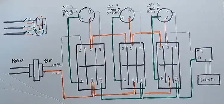
1311 Valve Wiring Terminals Identification
Terminal identification of a simplified 1211 Zone Valve circuit:
TERMINALS 1, 2: POWER TO VALVE
- Pin 1: 24VAC Neutral
- Pin 2: 24VAC HOT
TERMINALS 5, 4, 6: SPDT THERMOSTAT
- Pin 5: Power (Same as 2 Internally)
- Pin 4: Opens Valve
- Pin 6: Closes Valve
TERMINALS 2, 3: AUXILIARY SWITCH
- 2, 3 Become Same Point on Call for Heat
TERMINALS 1, 3: POWER OUT TO AUXILIARY
- The circuit on Call for Heat
Wiring Connection in White Rodgers 1311 Zone Valve
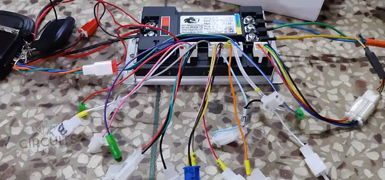
The 1311 utilizes a straightforward terminal block wiring harness for simple integration. Here are the key connection points:
- Terminals 2 and 2: Both provide power to the valve, receiving 24VAC voltage, one supplying the neutral and the other the hotline.
- Terminals 5, 4, and 6: These cater to the Single Pole Double Throw (SPDT) thermostat connection. Terminal 5 carries the power (shared with terminal 2) while terminal 4 activates valve opening and terminal 6 triggers closure.
- Terminals 2 and 3: These serve as an auxiliary switch, merging into a single point when the thermostat calls for heat.
- Terminal 3: This becomes the power outlet to the auxiliary circuit once the thermostat demands heat.
Navigating the Wiring Diagram
The wiring diagram serves as the roadmap for installation and operation. It visually represents the electrical connections between the valve, thermostat, and power source. Installing the 1311:
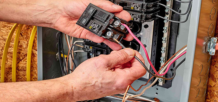
- Safety First: Disconnect the power at the main breaker box and drain the water system.
- Mounting Matters: Choose a level location near the boiler or manifold and secure the valve firmly.
- Plumbing Connections: Connect the hot water supply to the inlet and individual zone piping to the outlets.
- Wiring Wisdom: Refer to the diagram and meticulously connect wires to corresponding terminals. Double-check for tightness and polarity.
- Power Up: Restore power and test the valve by adjusting the thermostats in each zone.
- Testing and Verification: Ensure hot water flows to the desired zone when the thermostat calls for heat.
Troubleshooting Common Issues
- Valve not opening: Verify power connections and the thermostat’s demand for heat.
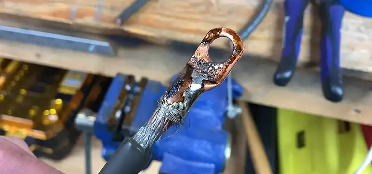
- Valve leaking: Tighten connections or replace the valve if necessary.
- Valve making noise: Seek professional assistance, as this could indicate motor or internal component issues.
Ensuring Longevity
Regularly wipe the valve with a damp cloth and inspect for leaks or damage. Address any issues promptly to guarantee optimal performance. Consult a Professional if you are unable to handle the repair yourself.
FAQs – Frequently Asked Questions and Answers
- Is the existing thermostat compatible with the 1311?
Answer: Compatibility depends on the thermostat being low-voltage friendly. Check its specifications for confirmation.
- What size zones can the 1311 valve handle?
Answer: The 1311 is suitable for individual zones with a maximum load of 1,000 BTU/h per zone. For larger zones, consider using a different zone valve model with a higher flow capacity.
- Is it possible to use multiple zone valves in the existing system?
Answer: Yes, you can install multiple 1311 zone valves in your system to control individual zones independently. Each zone will require its valve and thermostat.
To Conclude
By understanding the White Rodgers 1311 zone valve wiring diagram, you can unlock its potential for a comfortable and efficient heating system. Remember, safety and proper installation are paramount. With this guide, you can take control of your heating and enjoy optimal comfort in every zone.
Subscribe to our newsletter
& plug into
the world of circuits
![[Answered] Can I Use 12/2 Wire For Lights?](https://www.circuitsgallery.com/wp-content/uploads/2023/12/Can-I-Use-12-2-Wire-For-Lights.webp)
![[Explained] What Gauge Is Telephone Wire?](https://www.circuitsgallery.com/wp-content/uploads/2023/11/What-Gauge-Is-Telephone-Wire.webp)