How to Build a Bridge Rectifier for an AC Welder | Explained with Step-By-Step Instructions
A bridge rectifier is an apparatus that converts alternating current to direct current. A bridge rectifier is used to rectify the alternating current power source, resulting in a steady and constant DC voltage appropriate for welding. In this article, we will go through how to build a bridge rectifier for an AC welder in great detail.
Building a Bridge Rectifier for an AC Welder
A proper rectifier can be made if you have the proper tools and knowledge. From safety to planning to wiring everything has to be done cautiously. Here are the required materials and instructions to build a bridge rectifier for an AC welder.
Required Materials and Tools:
- Four diodes (typically 1N400x series diodes, where “x” represents the diode’s specific part number. Example: 1N4007)
- The heat sink
- Soldering iron and solder
- Insulated wires
- Electrical tape or heat shrink tubing
- Screwdriver
- Wire strippers and cutters
- AC welder with AC output terminals
Instructions:
Before working on any electrical wiring, the power supply should be turned off at the circuit breaker or disconnected. Here are some instructions to build a bridge rectifier for an AC welder:
- The diodes need to be connected in a bridge rectifier configuration. Here are the steps to do so:
- First, join the cathode of the first diode to the anode of the second diode. Then, connect the anode of the first diode to one of the welder’s AC output terminals.
- Next, join the anode of the second diode to the anode of the third diode and connect the cathode of the second diode to the other AC output terminal on the welder.
- Finally, connect the cathode of the third diode to the cathode of the fourth diode and connect the anode of the fourth diode to the common ground, which is typically the metal chassis of the welder.
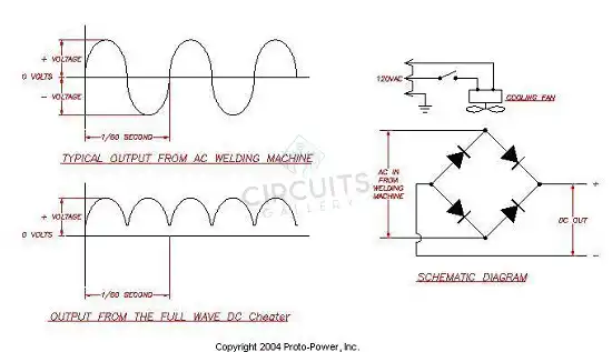
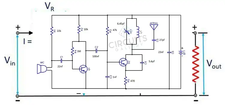
Figure 1: A simple bridge rectifier circuit
- Attach the diodes to the heat sink using thermal paste or adhesive if necessary.
- Check that all connections are secured. The diode connections can be protected to avoid short circuits using electrical tape or heat shrink tubing.
- Double-check all connections so that there are no loose wires or exposed conductors.
- Reconnect the welder to the power source and test it. Make sure to follow all safety precautions and use appropriate welding equipment.
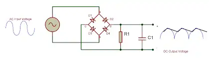
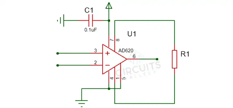
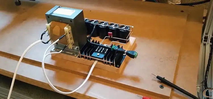
Figure 2: A loaded bridge rectifier circuit
Frequently Asked Questions
What is an AC-to-DC Rectifier for a Welder?
An AC-to-DC rectifier is an essential part of every welding equipment. It transforms the alternating current power supply into a DC welding current, which is required for most welding applications. This rectifier is suitable for stick, MIG, TIG, FCAW, and CAC-A welding.
Why is DC Preferred over AC in Welding?
DC produces a smoother weld with less spatter because of the continuous direction of the current. It also welds thinner materials better than AC, working best with stick welding, stainless steel TIG welding, and vertical or overhead welding.
How to Convert AC to DC Using a Rectifier?
While a rectifier is in operation, only one direction of current flow is permitted, and the other direction is barred. Diodes, electrical components that act as one-way valves, can be used to do this.
Conclusion
With the proper tools and knowledge, a bridge rectifier can be built. However, doing any electrical work has a lot of potential risks. Therefore, proper caution and safety measures should be followed and it’s best to seek the assistance of a qualified electrician or engineer to ensure safety and integrity.
Subscribe to our newsletter
& plug into
the world of circuits