Are Transistors Analog or Digital | Differences And Configurations
Transistors are inherently analog. But they can also function in digital circuits. Their functioning depends on their specific application and configuration.
In analog circuits, transistors are utilized to amplify and control continuous signals. It allows smooth variations of voltage or current. In digital circuits, transistors are employed as switches to represent binary states (0 or 1). It enables the processing and manipulation of digital information.
What Is the Difference Between Digital and Analog Transistors
The functioning of a transistor in a circuit determines whether it is analog or digital.
Digital Transistor
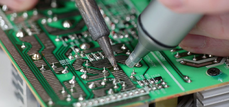
Digital transistors are also switching transistors. These are specifically made for digital circuit applications. They are primarily used to control the flow of current as on/off switches. Logic gates, CMOS transistors, and bipolar junction transistors (BJTs) are common examples of digital transistors.
Analog Transistor
Analog transistors, on the other hand, are most commonly seen in analog circuits. Continuous signals are amplified, modified, or processed using them. They are intended to mimic the properties of the input signal precisely. It provides for smooth changes in voltage or current.
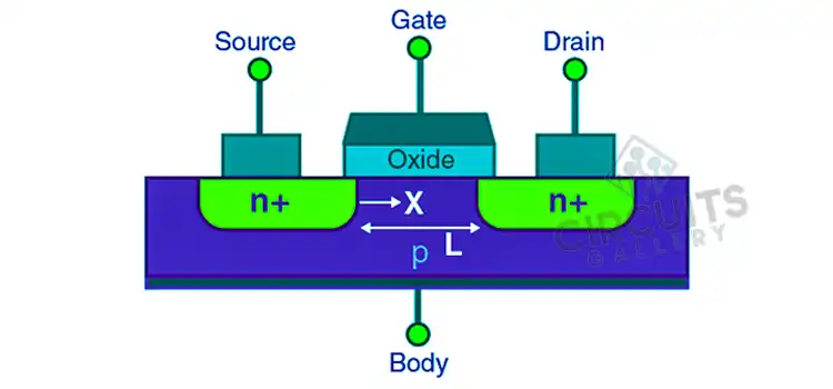
Common examples of analog transistors include operational amplifiers (Op-Amps) and Field-Effect Transistors (FETs). FETs are used in audio amplifiers, voltage regulators, and other analog circuits.
How Does the Configuration Determine Whether the Transistor Functions In an Analog or Digital Circuit
The configuration of a transistor plays a significant role in determining whether it functions in an analog or digital circuit. The two common configurations are as follows:
- Common Emitter (for analog) and Common Collector (for digital)
In the common emitter configuration, the transistor is used as an amplifier. It amplifies small variations in input voltage or current, providing a continuous output signal that faithfully replicates the input.
In the common collector configuration (also known as emitter follower), the transistor is used as a voltage buffer or impedance matcher. It allows the input signal to control the output voltage without inversion, serving as a voltage level translator.
- Common Base (for analog) and Common Emitter (for digital)
The common base configuration is often used in high-frequency applications. It provides current gain and has a good input-output phase relationship.
The common emitter configuration is commonly used in digital circuits. It acts as a switch, allowing or blocking the flow of current based on the input signal. It exhibits clear on/off behavior and is widely employed in logic gates and digital signal processing circuits.
Are there any specific transistor parameters that differentiate analog and digital transistors?
While there is no strict differentiation between analog and digital transistors, certain parameters may vary. Analog transistors often emphasize linearity, low noise, and high gain. And digital transistors prioritize fast switching, low saturation voltage, and high noise immunity.
Conclusion
The same transistor can be used for amplification in analog circuits and as a switch in digital circuits. You have to adjust the biasing conditions and operating parameters such as voltage levels and input signals, for this purpose. Certain transistor types are commonly associated with either digital or analog applications.
Subscribe to our newsletter
& plug into
the world of circuits

![How to Run a 12V DC Motor on 120V AC [Step-by-Step Guide]](https://www.circuitsgallery.com/wp-content/uploads/2023/10/How-to-Run-a-12V-DC-Motor-on-120V-AC.webp)