555 Touch Sensor
How to make a touch sensor? Here is a simple DIY touch sensor circuit diagram using 555 timer monostable mode. The touch switch is only a conducting metal sheet that acts as a touch sensor. The 555 touch switch is not a touch capacitive sensor; it is only a metal touch sensor button. Using this you can turn on and off devices with a single touch. Here we are using a JK flip flop IC 7476 that is connected as a T-flip flop. The output of the T-flip flop is connected to the base of the transistor to turn ON the relay so as to control high-current electrical devices such as fan, motor, lamps, etc.
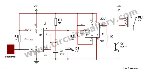
Circuit Diagram of 555 Touch Switch
Components for 555 Touch Sensor
- IC 555
- IC 7476
- Transistor BC 548
- LED
- Resistor (1M,1K,330)
- Capacitor (0.1uF)
- Touchpad (Any conducting sheet)
- Relay 12V,10A
Working Procedure of 555 Touch Sensor
- The 555 timer IC is connected in monostable mode, i.e. 6th and 7th pins are shorted, a capacitor is connected to the ground and a resister is connected to Vcc.
- The working of this circuit is the same as that of a monostable multivibrator.
- When we touch on the touchpad, a negative voltage is produced on the trigger pin (2nd pin) of 555 IC. Then monostable output goes high.
- The touchpad is only a conducting metal sheet.
- If your circuit is not working then you have to connect a 1M resistor from the 2nd pin of 555 to Vcc (+5V).
- The output of 555 is connected to the clock of JK flip flop IC 7476.
- Here JK flip flop is connected as a T flip flop (toggling mode) depending on the clock.
- Its state will change by applying a clock signal, i.e. if the output of JK flip flop is high, it changes to low else it will change to high.
- The output of the T flip flop is connected to the base of the transistor BC 548 through a 1K resistor.
- A positive voltage on the base of the transistor will forward bias the transistor, then the relay gets negative and it switches the device.
Subscribe to our newsletter
& plug into
the world of circuits

![What Is a Main Lug Panel? [Answered & Explained]](https://www.circuitsgallery.com/wp-content/uploads/2023/11/What-Is-a-Main-Lug-Panel.webp)