Lab Scope vs Oscilloscope | Key Differences
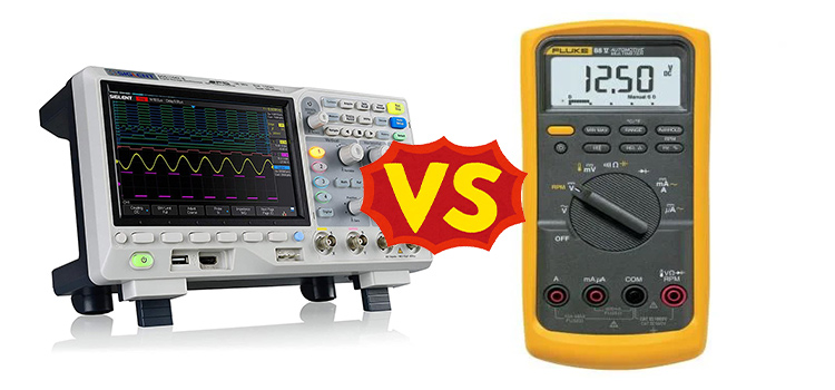
Lab scope or oscilloscopes are widely used equipment in solving complicated and difficult circuit problems, especially in electronics. In case you are wondering which scope is better, this article will give you a clear insight into the differences in their functionality.
An oscilloscope builds electric waveforms of the input signal as a function of time and displays them on its screen which would otherwise occur too briefly to measure by a human eye. A lab scope is generally used to measure and analyze automotive electric signals.
Difference Between Lab Scope and Oscilloscope
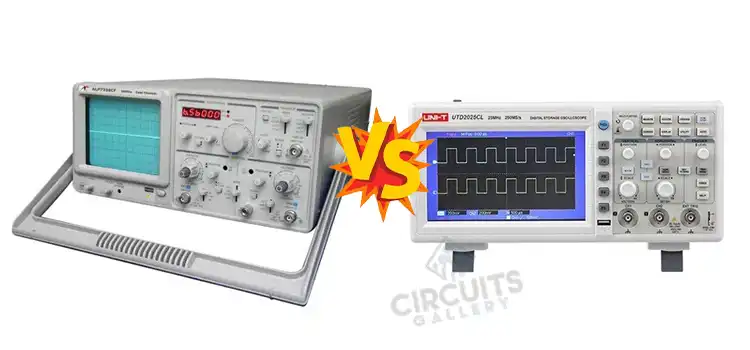
Although both the word ‘lab scope’ and ‘Oscilloscope’ often refers to the same thing, there are a few key differences between a lab scope and an oscilloscope.
What Is a Lab Scope
A lab scope is generally used to measure and analyze rapidly changing voltage levels in an electric system or a test module operation, monitor chemical or biological reactions, etc. It is smaller in size than an oscilloscope. In automotive electronics, lab scope is considered the ‘Tool of the decade’.

4-Channel Pico 4425A MASTER lab scope
4-Channel Pico 4425A MASTER Diagnostic Kit (PQ194)
What Is an Oscilloscope
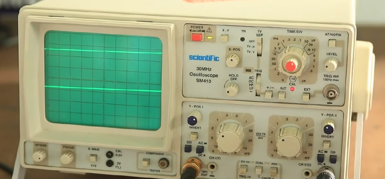
An oscilloscope is a test device that not only measures voltages but also creates a waveform of that signal on the display. This displayed waveform can later be analyzed for properties like frequencies, amplitude, time interval, etc. An oscilloscope can either be analog or digital. Oscilloscope has a very versatile use.
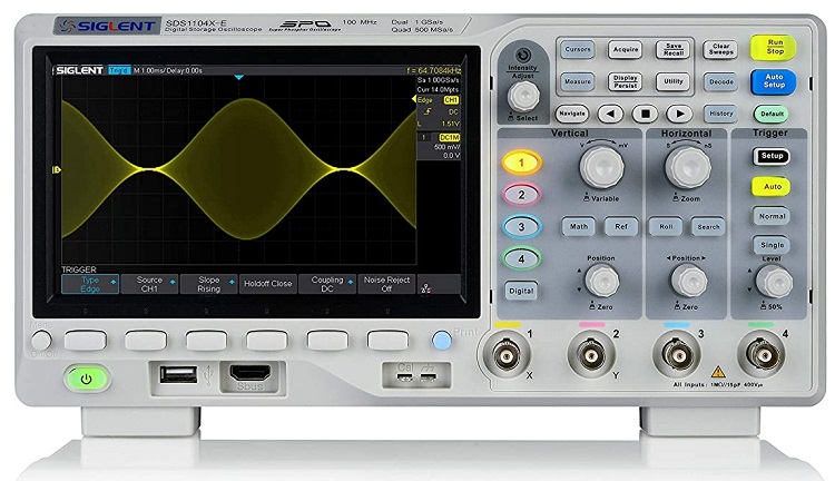
4 Channel digital Oscilloscope
Siglent Technologies SDS1104X-E 100Mhz digital oscilloscope 4 channels standard decoder, Grey: Amazon.com
Is a lab Scope an Oscilloscope
In electronics, the word lab scope or oscilloscope often refers to the same instrument. Sometimes, an oscilloscope is referred to just as a scope. Scope is used as a common term. However, the word lab scope may also refer to a laboratory microscope.
Lab Scope Overview
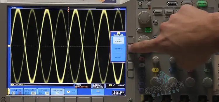
A lab scope has many functionalities. It is easy to use. It provides a satisfactory and instant result in measuring rapidly changing voltage. A lab scope has simplified knob controls and switch systems. So, a user can easily work with this device. It has a wide bandwidth. It is widely used in automotive electronics.
An automotive lab scope allows you to capture videos and images of the electronic signal. It also has an internal storage facility. One can easily store the data and results for later use. Storage can also be expanded by inserting an external SD card. It can transfer data through USB and can also be connected to a pc or laptop.
How Fast Can a Lab Scope Take a Sample
In automotive electronics, it is essential to have a very high sample rate. The more sample rate a device has, the more accurately it can measure and analyze signals. If a lab scope has an insufficient sample rate, it will not be able to measure the amplitude, time period, distortion other properties of the wave signals properly.
Sample rate means the number of samples a lab scope can perform per second. A lab scope can take samples very fast. Usually, a standard lab scope can take samples within a microsecond. An automotive lab scope has a 10 M/s sample rate. However, with more sample rates and bandwidth, more noises happen.
Oscilloscope Overview
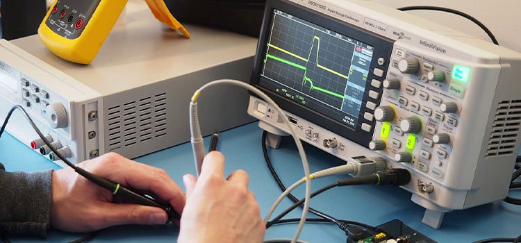
An oscilloscope is a voltage measuring test instrument. It is more than just a voltmeter. It creates a graphical waveform of the electronic signal. From this graphical image, one can dive deep into the roots of the problems. An oscilloscope has a number of channels that make the diagnosis faster and reduce noise.
The oscilloscope also has a wide bandwidth and input ranges. It is a bit complex to use. However, nowadays most of these devices have a one-touch automatic setup which made them very user-friendly. The waveforms of the signals can be stored for later analysis and transformed into digital signals.
Other Uses Of an Oscilloscope
Oscilloscope has a versatile application. Such as-
- To test circuits and troubleshoot problems.
- To find the voltage, frequency, time period, distortion of that electric signal.
- To detect noise in signals and its variation with respect to time.
- Separate AC and DC currents.
- To analyze an automotive ignition system.
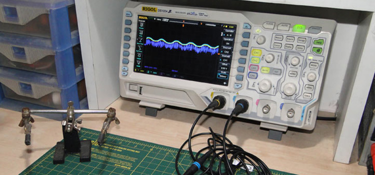
How Do You Use a 4 Channel Oscilloscope
There are countless electric signals and lots of varieties and models of an oscilloscope. So, the process won’t be the same for every signal and model. However, there are some common steps that are followed in every scope.
Probe Selection And Oscilloscope Setup
A 4 channel scope can work with 4 signals at a time. Each signal read by the scope is run into a separate channel. At first, you have to select a probe and set its attenuation. For most signals, a simple passive probe will do just fine. Connect your probe to channel 1 and boot up your scope. It might take some time.
After the screen is on, turn all the channel except channel 1 and set it to DC coupling. Set the trigger source to channel 1. Set the trigger type to the rising edge and trigger mode to auto. Now, make sure that the attenuation of your probe matches the scope’s probe setting. Now you have to test the probe
Probe Testing And Signal Adjusting
Most of the scope has a built-in frequency generator. Connect the probe tip to the signal output and the probe’s ground clip to the ground. Then a signal will pop up on the probe’s screen. Now adjust the horizontal and vertical scale with system knobs.
If the signal is unstable, rotate the trigger position knob to make sure that the trigger isn’t higher than the peak of the signal. If you do not get a perfectly squared shape due to low voltage decrease probe attenuation.
Is Hantek 1008c Any Good
Hantek 1008c is a very cheap 8-channel automotive oscilloscope. It is an entry-level scope. You can use it to perform small tasks such as signals and sensors testing, ignition waveforms, injector waveforms, bus detections, etc. It supports windows XP/7/8/10 and allows to record and replay the waveforms.
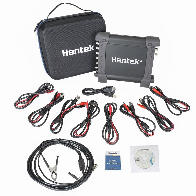
Hantek 1008C Automotive Digital Oscilloscope
Hantek 1008C PC USB 8CH Automotive Diagnostic Digital Oscilloscope/DAQ/Programmable Generator
It comes in a good package of scope units, 8 sets of alligator clips, a plug wire clamp, USB cable. It has a low bandwidth of 100 kHz and a low sample rate of 2.4MS/s. It has also a 4K memory which is very insufficient. Therefore, it is not that good. But considering the price, it can be a reasonable choice for light use.
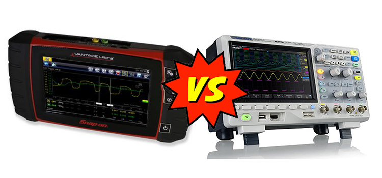
Which One to Choose
Both devices have unique features and useful applications. There are lots of variants and models available in the market. Hence, based on their functionality you have to pick the right one.
Frequently Asked Questions
Can You Measure Current With an Oscilloscope?
Most oscilloscopes only directly measure voltage. However, by applying some methods one can easily measure current with an oscilloscope. You can measure the voltage drop across a shunt resistor and then multiply it by the shunt’s resistance or you can use a current probe to measure the current.
Conclusion
Oscilloscopes are a very important tool in any electrical engineer’s lab. It allows you to inspect an electric circuit closely and thoroughly. In automotive diagnosis lab scope is considered to be the best.
Subscribe to our newsletter
& plug into
the world of circuits