Introduction to PLC | What and How
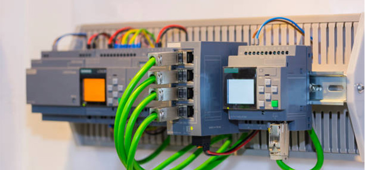
Ever wondered how huge factory machinery works on automation? These machines are mainly programmed to do tasks that are controlled by PLC. PLC stands for Programmable Logic Controller. It may not have all the fancy looks, but pack a whole bunch when it comes to operations. This is why automated factories use PLC for the most effective automations.
Today we are going to talk about PLC, its application and how it works.
What Is PLC?
PLC is used to control the function of the machine automatically. It is a computerized industrial microprocessor-based controller that executes discrete or sequential logic in an industrial environment. It was originally developed to replace mechanical relays, timers, and counters hence it is also called industrial PLC. A PLC has an integrated programmable microprocessor that is programmed with a dedicated computer language (Ladder Diagram). After writing the PLC program it is downloaded to the non-volatile memory of the Programmable Logic Controller directly through a cable connection via Serial or USB ports.
Difference between PLC and Microcontroller
- PLC is mainly used for industrial applications, PLCs allow end user to organize and control the application which is more helpful in industries. Very complex controls and process like chemical industries requires more re-configurable controls.
- Microcontroller design would be suitable where end user need not modify the controls eg: Automatic washing machine.
- PLC programming is a type of graphical programming called ladder diagrams which are simple to understand, extremely easy and customized.
- Microcontrollers are programmed using either Assembly language or C language. Compared to Ladder Diagram these are much complicated.
- Trouble shooting is easier in PLC than microcontroller via online programming (we can see the real time working of PLC through computer).
- PLCs are electrically based controllers but Microcontrollers are electronics based.
- PLC module is costly as comparing with microcontroller, thus PLCs are commonly used in industries where as microcontrollers are applied in simple applications due its low cost.
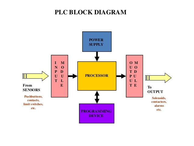
Block Diagram of PLC
Advantages of PLC
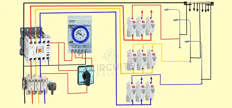
PLC has made a considerable role to Industrial automation. Former automation scheme had to use thousands of individual relays, timers and counters, which had to be rewired whenever we need a modification in the automated process. PLC permits all of the relays and timers within an industry to be replaced by a single controller. Present PLCs provide wide range of operations, including basic relay control, process control, motion control, and complex networking. They also be able to be used in a distributed control system (DCS).
Importance of PLC Programmer
- Attractive salary.
- Easy to work with PLCs.
- Easy to learn PLC programming (Ladder diagrams).
Applications of PLCs
- PLCs have a wide range of industrial applications, it is applied in
- Process Industry.
- Automotive Industry.
- Energy Monitoring and load Shedding.
- Oil & Gas Industry.
- Petro – Chemical Industry.
- Water Treatment Plant Etc.
Getting Started With PLC (Programmable Logic Controller) Omron
Would you like to learn PLC programming? In our previous article, we have seen what is PLC? Why it is used? Now we are going to discuss how to get started with PLC (Programmable Logic Controller)? Yes, CircuitsGallery (CG) provides you with online free PLC training courses. Our CG lab is equipped with the popular PLC system from OMRON.
Now let’s start our PLC classes to become a PLC (Programmable Logic Controller) programmer. This article will give you the basic configurations and hardware parts of OMRON PLC; it is simply a familiarization of PLC.
OMRON’s Sysmac CQM1 PLC is a perfect platform for those of you who are looking to attain real-time experience in PLC programming. We use CX-Programmer as OMRON PLC programming software to do PLC ladder logic. The work online PLC simulator option in OMRON PLC will allow you to test and simulate your own PLC-based projects. This is an OMRON PLC manual for free online PLC training.
Different Parts of an Omron PLC
- Power supply card (PA203)
- CPU
- Input cards
- Output cards
How to Setup Your Omron Plc- Inserting Power Supply Card
- In order to work with PLCs, you need a power supply circuit (24V). Sysmac CQM1 PLC comes with a dedicated Power supply card.
- Attach the power supply card to the CPU on the left side
- Then fix the Lock button. Now the PLC is ready with power, you can connect either 110V or 230V supply via this power supply card.
Inserting I/O Cards
- Sysmac CQM1 PLC has an integrated input card. If you need more than 15 inputs you can insert additional input cards. There will be an auxiliary card to close the internal circuitry of PLC.
- To insert an Output card first you need to remove the auxiliary card.
- Then insert the output card via the right side of PLC and lock it using the lock button provided on both sides.
- After that, attach the auxiliary card to close the internal circuitry. Now our PLC is ready with 1 integrated input card and 1 additional output card.
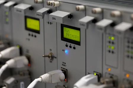
Power on your PLC
Turn ON the PLC power supply unit to start your PLC workshop!! After powering up, you will be able to see some indicator LEDs showing the status of active PLC.
- Status LED of the power supply unit
- Status LED of PLC CPU
- Input status: There will be 15 LEDs each of which glows when the corresponding input is active.
- Output status: Here are also 15 LEDs that glow according to the specific active output.
Conclusion
PLCs are somewhat similar to Microcontrollers i.e. user can write a program using a computer and burn it into the memory of the microcontroller via a cable. The OMRON PLC is more of a finished product that is ready to be programmed.
Subscribe to our newsletter
& plug into
the world of circuits