How to Make a LCD Controller Board? Step-by-Step Guide
LCD displays are used in a wide variety of devices from small embedded systems to large format monitors and TVs. At the heart of driving these displays is the LCD controller board. The controller board takes in image data from a source like a computer, converts it to signals the LCD panel can understand.
Building your own LCD controller board is an advanced electronics project but can be a great learning experience. In this article, we’ll walk through the basics of assembling a DIY LCD controller.
Components Required to Make an LCD Controller Board
To make an LCD controller board, you will need the following components:
- Microcontroller board (e.g. Arduino Uno)
- LCD driver IC (e.g. SSD1963)
- Voltage regulator (e.g. 7805)
- Oscillator/crystal (8MHz: 25MHz)
- Resistors (10K, 330 ohm)
- Capacitors (0.1uf, 10uf)
- Headers and jumper wires
- Project Board or protoboard
Additional helpful supplies include a solder, wire, multimeter, oscilloscope, and an LCD panel for testing.
Step-by-Step Procedure for Making an LCD Controller Board
The following procedure will guide you in creating an LCD Controller Board systematically:
Step 1: Plan the Circuit
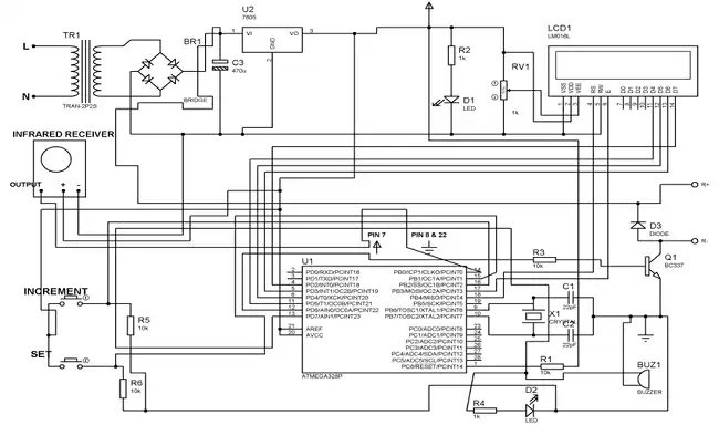
The first step is to design a schematic diagram for the controller board circuit. This will map out the connections between all components.
The main components to include are:
- Microcontroller to generate image data
- LCD driver IC to handle panel interface
- Oscillator for timing signals
- Voltage regulator for clean power
- Supporting resistors and capacitors
Step 2: Prototype on the Breadboard
Before soldering, prototype the circuit on a breadboard to test operation. This allows quick reconfigurations if needed.
- Insert components into the breadboard following the schematic.
- Double-check all connections and orientations.
- Connect programming wires to the microcontroller.
Step 3: Write Test Code
With the breadboard prototype wired up, write a simple Arduino test code to initialize the LCD driver IC and send a test image pattern such as,
#include <Adafruit_GFX.h>
#include <Adafruit_ILI9341.h> // Use the appropriate library for your LCD driver IC
#define TFT_CS 10
#define TFT_DC 9
#define TFT_RST 8
Adafruit_ILI9341 tft = Adafruit_ILI9341(TFT_CS, TFT_DC, TFT_RST);
void setup() {
  // Initialize the display
  tft.begin();
  tft.setRotation(3); // Adjust the rotation if needed
  // Fill the screen with a background color
  tft.fillScreen(ILI9341_BLACK);
}
void loop() {
  // Set the drawing color and draw a test pattern (in this case, lines)
  tft.setTextColor(ILI9341_RED);
  tft.fillScreen(ILI9341_BLACK);
  for (int x = 0; x < tft.width(); x += 6) {
    tft.drawLine(x, 0, tft.width() - x, tft.height(), ILI9341_RED);
  }
  delay(2000); // Display the pattern for 2 seconds
  // You can experiment with different test patterns and colors here
  // Clear the screen
  tft.fillScreen(ILI9341_BLACK);
  delay(1000); // Pause for a moment before the next pattern
}
This code will configure settings like resolution, polarity, and timing parameters on the LCD driver. Then it can send a basic bitmap image out to the display.
Step 4: Verify Functionality
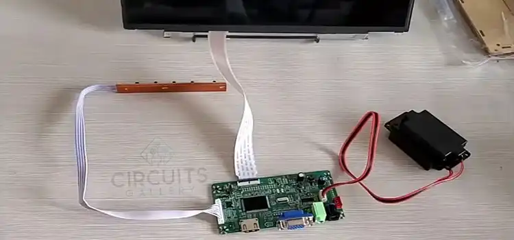
Connect the LCD panel to the breadboard prototype and run the test code.
- Check that the LCD powers on and displays the test pattern.
- Monitor the signals on an oscilloscope to verify they are correct.
- Make any needed adjustments to the code or circuit.
Step 5: Design the PCB Layout
Once the circuit is fully tested and functional, you can design a PCB layout for the LCD controller.
Use PCB design software to arrange the components and route the copper traces between them according to the schematic diagram. The PCB layout should match as closely to the prototyped breadboard circuit as possible.
Consider component placement carefully to minimize noise and interference. Route high-speed traces in tight, controlled impedance paths.
Step 6: Order and Assemble the PCB
Send the finished PCB layout files to a fabrication service to get the boards manufactured.
Once received, populate the PCB by soldering on all required components in their designated places. Work carefully and double-check orientations.
Step 7: Write Display Driver Firmware
With this PCB assembly, write the main firmware for driving graphics to the LCD.
This will build on the test code to implement functions like:
- Framebuffer management
- Bit blit operations
- Color space conversions
- Geometric transformations
- Font/text rendering
- Backlight control
The firmware should have enough functionality to display full-screen graphics, text, shapes, images, etc.
Step 8: Install and Test the LCD Controller
The LCD controller board is now ready to be installed and tested:
- Carefully mount the assembled PCB and connect it to the LCD panel.
- Connect it to the microcontroller programming cables.
- Power it on and run demo programs to test all display functions.
Make any final adjustments as needed until the controller is operating reliably.
Frequently Asked Questions (FAQs)
1. What is the Hardest Part of Making an LCD Controller Board?
Answer: The most challenging aspect is usually designing and writing the firmware to properly initialize the LCD driver IC and then implement graphics functions like rendering, transformations, and framebuffer management.
2. What Tools are Needed to Make an LCD Controller Board?
Answer: Basic electronics assembly tools like a soldering iron, multimeter, wire cutters, etc. For testing and debugging, an oscilloscope and signal analyzer are very helpful. PCB design software is needed for the board layout.
3. Is the LCD Controller Board Universal?
Answer: Yes, an LCD Controller Board is universal for all LCD displays which supports a Controller Board.
To Conclude
Building a custom LCD controller board from scratch is an advanced but rewarding electronics project. With some diligent work, you can create a quality DIY LCD controller and gain valuable experience with embedded systems development in the process. Just be sure to test thoroughly at each stage of development.
Subscribe to our newsletter
& plug into
the world of circuits
![What Does Current 0 Mean [You Need to Know]](https://www.circuitsgallery.com/wp-content/uploads/2023/08/What-Does-Current-0-Mean.webp)