555 Timer IC Audio Amplifier Circuit Schematics
Here we are going to discuss a simple timer IC 555 project. The 555 timer IC can be used as an audio amplifier with an astable multivibrator configuration. It functions to carry out pulse width modulation (PWM) of the audio signal. The Current(I) capacity of the 555 timer amplifier is 200mA which is sufficient to drive a small speaker. This simple 555 IC-based amplifier circuit is a good substitute for conventional low-power amplifiers. The low-frequency audio signal is applied to the control voltage pin (5th pin) of 555 for pulse width modulation (PWM) generation. For beginners who want to know ‘what is PWM?’,
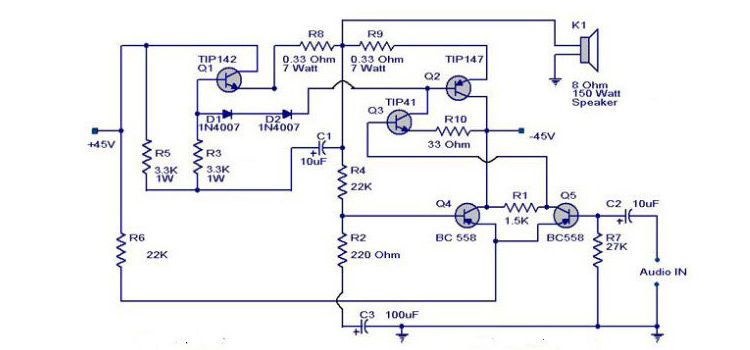
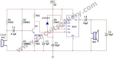
Circuit Diagram of 555 Amplifier
Components Required
- Power supply
- Resistors (1kΩ x 2; 10kΩ; 47kΩ; 100kΩ; 680kΩ)
- Capacitors (10pF; 0.1µF, 1µF, 10µF x 2)
- Transistor (BC547)
- Timer IC 555
- Condenser mic
- A loudspeaker (8Ω)
Working Principle
- The circuit is based on an astable multivibrator circuit using 555 timer IC, the working principle of which we had already posted.
- In the normal mode, we just open the circuit the 5th pin (Control voltage pin) of 555 IC. But the most interesting fact we often neglect is that if a low-frequency signal is applied to the 5th pin of 555 IC, pulse width modulation starts.
- Here the oscillating frequency of 555 astable is approximately 145 kHz. The discharge time of capacitor C3 via diode 1N4007 is too fast since there is no resistor to discharge.
- The condenser MIC is used as a transducer to sense the incoming audio signals and convert them to proper electrical signals.
- The output of the MIC is then fed to the transistor Q1 via a capacitor C1. This capacitor is used to remove the DC component of the signal.
- Resistor R1 provides the necessary biasing to the condenser microphone. And the resistors R2 and R3 give potential divider bias to the BC547 transistor.
- The capacitor C2 and resistor R4 provide negative feedback to the transistor circuit which is essential for amplification.
- The pre-amplified audio signal is fed to the control voltage pin of 555 timer astable multivibrator running with 145kHz.
- The process of pulse width modulation starts and as we know the speaker does not respond to this high frequency, it responds to the usual DC value of the modulated output. Hence the audio signal gets amplified.
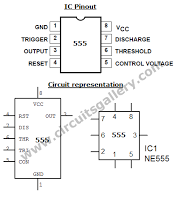
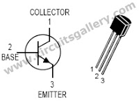
Pin Outs of Timer IC 555 and Transistor Bc547
Conclusion
Here, you get a brief idea about the 555 Timer IC Audio Amplifier Circuit. It is easy to make and can be used where audio amplification is required.
Subscribe to our newsletter
& plug into
the world of circuits