How to Solder Wires to Connectors
Remove the insulation of the wire and then pre-tin it. Insert the wire into the connector pin and make it hot enough by using a soldering iron. Apply solder to the pin until it is filled with it without overspilling. Wait for the solder to cool down.
The most common connector used Is the connectors with cup-type pins. One can easily insert the wire inside of the pin and solder without any need for a mechanical connection.
How to Solder Wires to Connectors
Here is a step-by-step guide to solder wires to connectors so that you do not get lost.
Step 1: Remove the Insulation of the Wire
To get started, remove the insulation from the end of the wire. You can use wire strippers and remove around ¼” or 6.3 mm of insulation.
Step 2: Tin the Wire
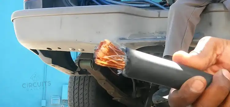
The next step is to tin the wire. The wire is coated with a thin layer of solder during tinning. Use a hand tool to hold the wire and apply a bit of rosin flux on the wire. Use a soldering iron to touch the exposed end of the wire and melt the flux.
Step 3: Apply Solder
Once the wire is hot enough, apply solder to the point of contact between the wire and the soldering iron. Avoid the mistake of doing that at the tip of the soldering iron directly.
When it comes to connectors, we are dealing with pins and thin wires. Therefore, using a solder wire with a medium diameter will suffice. For the tinning of thicker wires, you should use a solder wire that has a bigger diameter.
Step 4: Trim the Excess Wire
In this step, you have to insert the tinned wire into the pin and measure the actual length of the wire end. Whatever comes as excess, you have to trim it. Moreover, you should provide the proper insulation clearance which should be around one to two times the diameter of the wire.
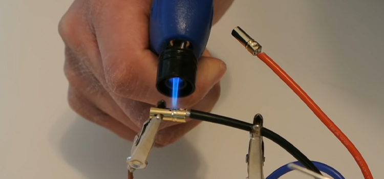
Step 5: Apply Solder to the Pin
Hold the connector using a small vice. One hand of yours will hold the soldering iron while the other one will hold the wire. Now place the soldering iron tip to the pin of the connector and make sure the contact is maximum.
Once the connector pin is hot enough, it will melt the solder. Then apply solder to the inside surface of the pin so that it is covered with solder and surrounds the wire. However, do not fill the pin with so much solder that it will overspill.
Step 6: Insert the Wire
Keep holding the soldering iron tip on the pin and insert the wire quickly. Push it in until the wire’s insulation reaches the end of the pin. Add a little bit more solder so that there is no empty space inside the pin.
Step 7: Remove the Soldering Iron
The last step is to remove the soldering iron and clean any excess solder or flux by using a moist sponge. Right after a few seconds, the solder will solidify and cool down. The result you will see is strong and bright soldering joint.
Conclusion
Soldering wires to connectors can be a bit tricky and lengthy process. You might need a helping hand to properly do the job. The pins in the connectors have little space around them and require extra attention. Therefore, make sure you follow the instructions discussed above and ask for professional assistance if needed.
Subscribe to our newsletter
& plug into
the world of circuits

![Will a 120V Photocell Work on 12V DC [Answered]](https://www.circuitsgallery.com/wp-content/uploads/2023/10/Will-a-120V-Photocell-Work-on-12V-DC.webp)