How to Identify Bad Capacitors
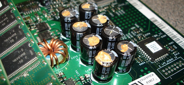
There are numerous ways to test a capacitor to verify if it still works properly. Though you can also identify a bad capacitor just by looking at it. If the capacitor has a bulging bottom or a lifted case, it is bad.
Broken or cracks in the casing, damaged or any sign of burnt casing, a hole in the casing, or broken terminals mean that the capacitor needs to be changed. To check capacitors in proper ways, you will be needing some instruments including a multimeter.
How to Identify Bad Capacitors
Capacitors, along with batteries, are the most prone to failure of UPS components. Capacitors deteriorate with age, diminishing their capacity to fulfill their function. Inside the capacitor, the electrolyte, paper, and aluminum foil die physically and chemically. To identify a bad capacitor, the following methods are used.
Using Digital Multimeter – Resistance Mode
Make sure that the capacitor is completely discharged. Set the meter to the Ohmic range (at the very least, 1000 Ohm = 1k). Connect the probes of the multimeter to the capacitor terminals (Negative to Negative terminal and Positive to Positive terminal).
For a split second, a digital multimeter will display some figures. Take note of the reading. Then it will immediately return to the OL (Open Line) or infinity. Every try of setting the meter will show the last readings. It indicates that the capacitor is in good condition. If there is no Change, then the Capacitor has died.
Using Analog Multimeter – Ohm Mode
Make that the suspected capacitor is completely discharged. Take an AVO meter with you. Toggle the analog meter’s knob to the resistance “OHM” mode (Always, select the higher range of Ohms). Connect the leads from the meter to the capacitor terminals. (COM to the “-Ve” terminal and Positive to the “+Ve”)
Take note of the reading and compare it to the results below. The resistance of a shorted capacitor will be very low. An open capacitor has no movement (deflection) on the OHM meter scale. It will exhibit low resistance at first, then gradually increase to infinity. It indicates that it is in good working order.
Using a Digital Multimeter with Capacitance Setting
Take the capacitors out of the circuit board. Now On the multimeter, select Capacitance “C.” Connect the capacitor terminal to the multimeter leads at this point. If the reading is close to the capacitor’s actual value (i.e. the printed value on the Capacitor container box).
The capacitor is then in good working order. (Please keep in mind that the reading may be less than the actual value of the capacitor (the rated value of the capacitor owing to tolerance in 10 or 20). If you read a substantially lower capacitance or none at all, the capacitor is dead.
Using a Simple Voltmeter
Only one of the two leads should be disconnected from the circuit. Now, check the voltage rating of the capacitor. Then, charge the capacitor with a known voltage that is lower than but near its rated value. Set your voltmeter to read DC voltage (if it can read both AC and DC voltage).
Connect the leads of the voltmeter to the capacitor. Take note of the first voltage reading. This should be close to the voltage you used to charge the capacitor. If it isn’t, the capacitor isn’t working.
By Measuring the Value of Time Constant
Connect a known resistance value in series with the capacitor. Apply a known supply voltage to a capacitor linked in series with a 10k resistor. Now, time how long it takes the capacitor to charge to 63.2 percent of the provided voltage. Calculate the value of capacitance using the Time Constant formula (τ = R x C).
based on the value of the provided resistor and the time measured with a stopwatch (Time Constant). Now, compare the computed capacitance value to the capacitor value displayed on it. If they are equal to or close to, the capacitor is in good condition. If you see a significant discrepancy in both numbers, it’s faulty.
Using Continuity Test Mode
Using a resistor, fully discharge the capacitor. Set the multimeter to continuity test mode by turning the knob. Connect the positive probe to the Anode (+) terminal of the capacitor and the common probe to the Cathode (-) terminal. If the multimeter displays a sign of adequate continuity before abruptly stopping and displaying an OL (open line), it indicates that the capacitor is in good working order.
If the multimeter does not display a continuity signal with a beep or led, the capacitor is open. If the multimeter LED illuminates and emits a constant beep sound, the capacitor is short and should be changed.
Conclusion
If you wish to test a capacitor without desoldering it, you should know that testing without desoldering is only possible by measuring their equivalent series resistance (ESR). Because there are a lot of other components in series or parallel with it.
Subscribe to our newsletter
& plug into
the world of circuits
![What Is Balanced And Unbalanced Output In Op-Amp [Answered]](https://www.circuitsgallery.com/wp-content/uploads/2023/08/What-Is-Balanced-And-Unbalanced-Output-In-Op-Amp.jpg)