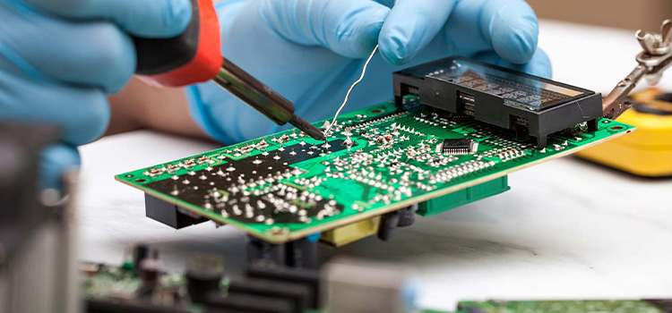
How to Solder Wires to a Circuit Board
To solder wires to a circuit, you have to heat the wire by touching it to a properly sized solder iron tip. Once the wire is hot enough, add solder to the wire without using the soldering iron directly to melt the solder.
The trickiest part of this job is the handling of soldering iron. That is why the person involved should be careful not to touch the hot soldering iron tip or the solder directly.
How to Solder Wires to a Circuit Board
Soldering wires to a circuit board is pretty simple once you know how to do it properly. In this section, we will discuss exactly which steps you have to follow.
Step 1: Preparation
To get started, you will need a solder. You can find them in different thicknesses from around 0.02 mm. For detailing and repairing jobs, you should opt for thin solder.
The next part of the preparation is to get a quality soldering iron to generate the most suitable temperature. Low wattage soldering irons between 15-40 watts are the best for soldering components on a circuit board.
Another important thing is the soldering iron tips. Rather than depending on temperature regulation, you should always use the biggest soldering iron tip that will fit into the area to be soldered. A bigger soldering iron tip will give you more heat energy in the quickest amount of time.
Working with a soldering iron has risks involved, therefore you have to be prepared with proper gear. Make sure you get yourself hand gloves, work boots, and safety goggles.
Step 2: Heat the Wire
The exposed wire should be cut to length at first. Then touch the soldering iron tip to the wire. Hold the tip for 2-10 seconds to make the cables hot enough. But make sure they do not melt.
At this point, the wires should be hot enough to melt the solder. You can test whether they are hot enough by touching the solder to the wires periodically. However, do not make the mistake of touching the solder to the tip of the iron as it causes a cold solder joint.
Step 3: Add Solder
Once you see that after touching the solder to the wire, it begins to smoke and melt, then the wires are hot enough. Place the soldering iron on the underside of the board so that it touches the metal around the hole and the wire at the same time.
Now, upon touching the soldering iron to the pad and wire from the opposite side, the solder will start flowing around the pad and the wire swiftly. However, do not make the mistake of using the soldering iron directly to melt the solder.
Step 4: Remove the Soldering Iron
Once you have decided that there is enough solder on the joint, it is time to pull the solder away. Then withdraw the soldering iron and pre-tin it for the next wire.
Conclusion
Knowing how to solder wires to a circuit board is a valuable skill for anyone involved with electrical jobs. It can also save you a fair amount of money. Moreover, there is little risk involved if you know how to do it correctly. However, always make sure that you are properly equipped.
Subscribe to our newsletter
& plug into
the world of circuits