AC vs DC Coupling Oscilloscope
DC coupling allows for observing all signals from 0 Hz to the scope’s maximum bandwidth. DC components are filtered out via AC coupling.
When we utilize an ac coupling on an oscilloscope channel, it acts as a low pass filter, filtering out the dc component of the signal.
The DC portion of the signal can be termed steady. As a result, ac coupling is said to block the steady component of the signal. Dc coupling, on the other hand, allows the observer to see the entire output signal.
Difference Between AC vs DC Coupling Oscilloscope
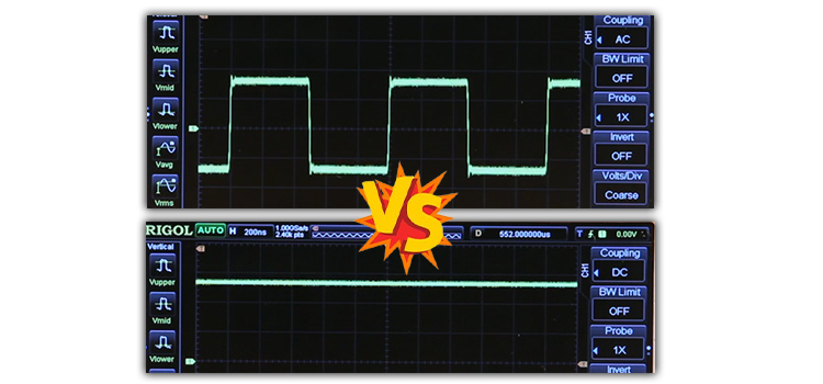
On occasion, modest voltage variations will need to be monitored. The stable voltage will be blocked by AC coupling, but fluctuations will be visible. When the voltage is a constant hundred volts, it’s impossible to notice a three-volt increase or decrease. AC connection enables the display to become magnified by blocking a hundred volts, allowing minor fluctuations to be seen.
On an oscilloscope, DC or AC coupling allows operators or engineers to focus on a specific part of the signal. The whole signal, including steady positive or negative voltages, is DC coupled to the screen. The stable voltage will be blocked by AC coupling, allowing you to see minor changes.
What is AC Coupling
The use of a capacitor to filter out the DC signal component from a signal having both AC and DC components is known as AC coupling. The capacitor must be connected to the signal in series.
AC coupling is advantageous because the DC component of the signal functions as a voltage offset, and eliminating it from the signal can improve signal measurement resolution. Capacitive coupling is another name for AC coupling.
What is DC Coupling
Both AC and DC signals can travel over a DC (direct coupling) connection. The DC component is a 0 Hz signal that serves as an offset for the signal’s AC component to vary around.
When to use DC Coupling
A direct coupling, also known as a DC coupling, is just a wire linked to the signal input. This conductive connection conveys both the DC and AC frequency components of the signal.
Dc coupling is required if all signals, including ac and dc, are to be monitored. That is, if we wish to examine a signal with zero frequency to its greatest bandwidth, we must employ dc coupling.
Is the Oscilloscope Connected to a DC or an AC Source
The oscilloscope’s waveform is primarily DC, with a small amount of AC “ripple” voltage visible as a ripple pattern on what would otherwise be a flat, horizontal line.
Most current oscilloscopes have the ability to automatically measure DC voltage. Manually measuring it by ‘counting’ the vertical reticules and multiplying by the volts per division is possible.
Why do we use AC Coupling in Amplifier Circuits
In amplifier circuits, coupling capacitors are critical components. They’re used to keep AC signals from interfering with a transistor’s bias voltage. The signal is driven to the base terminal of a transistor by a coupling capacitor in most amplifier circuits.
Frequently Asked Questions
What are the 3 types of coupling options in the oscilloscope
An oscilloscope has three primary control components. An oscilloscope’s front panel is separated into three sections: Vertical, Horizontal, and Trigger.
Conclusion
The major distinction between ac and dc coupling is that ac coupling does not allow the observer to watch the dc signal, whereas dc coupling allows the observer to monitor both the ac and dc signal. When operators wish to see both ac and dc voltages, dc coupling comes in handy. When we need to filter the dc signal, however, ac coupling comes in handy.
Subscribe to our newsletter
& plug into
the world of circuits
