Westinghouse AC Motor Wiring Diagram
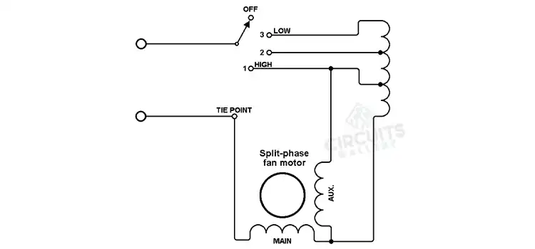
Some Westinghouse AC motors come with a start winding but no capacitor, while others come with a capacitor. You can depict the extra centrifugal switch as switching a function external to the motor.
When the motor is running, the extra contact on the starting centrifugal switch is shown as feeding power to an external function. The third wire is used to transmit the sensor’s common mode (CM) voltage to the receiving device.
Wiring Diagram of Westinghouse AC Motor
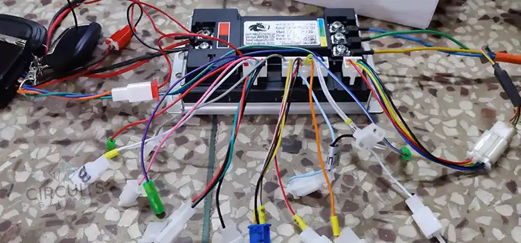
To wire a Westinghouse AC Motor wiring diagram, perform the following steps:
- Separate the motor from the press and add by most printers to run the press via belt and flywheel to speed up printing.
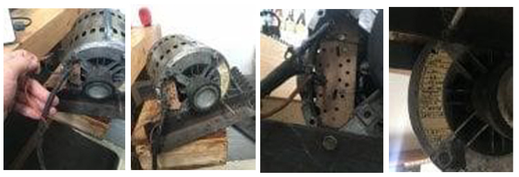
- Resurrect the motor by adding a proper ground wire and installing an on/off switch at the press (rather than at the motor). The motor is located behind the press, beneath the flywheel). The following images will help you better understand the process.
What Are the Three Wires on an AC Motor
The three wires for single phase AC motor and three-phase AC motor are given below:
Single-Phase AC Motor
The lead wire colors for a standard 3-wire motor are typically white, red, and black. Black is always associated with neutral (N). Both white and black are connected to the dedicated capacitor’s two terminals.
When the live (L) terminal is connected to either the black or red terminals via the capacitor terminal, the motor begins to rotate in the desired direction. The theory of operation is the same for terminal box-type motors.
Three-Phase AC Motor
We have the same wire colors for a three-wire three-phase motor. The three power supply phases are labeled L1 (R), L2 (S), and L3 (T). The red is connected to L1 (R), the white to L2 (S), and the black to L3 (B) (T).
The terminals on terminal box-type motors are labeled U, V, and W. The operation theory is the same. Switch any of the two connections between R, S, and T to change the rotation direction.
How Do You Wire a 3-Wire AC Motor?
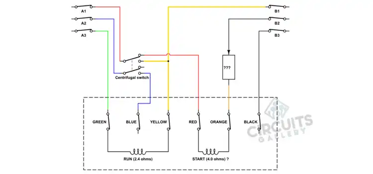
The wiring diagram of a 3-wire AC motor is given below:
Perform the following steps to wire a 3-wire AC motor:
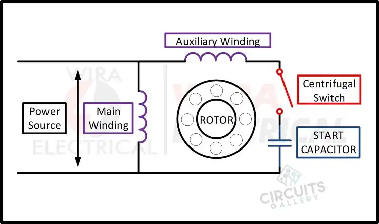
- Use the auxiliary winding is used to create an extra magnetic field. Of course, adding another winding will not affect rotating the rotor. A capacitor is used to shift the phase, resulting in two rotating magnetic fields of varying phases.
- The centrifugal switch connects the auxiliary winding to the capacitor and power supply. When the speed reaches a certain threshold, the switch disconnects the capacitor and auxiliary winding from the power supply.
- Only the main winding is energized from this point forward to keep the motor running in a steady state.
- Use the capacitor to switch between the start and run, we can call this a single-phase 3-wire electric motor capacitor switch or capacitor start induction motor.
How Do You Wire a 4-Wire AC Motor?
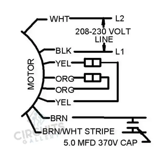
For the 4-wire connection:
- Connect the white wire from the condenser fan motor to one of the contactor’s power sides (T1).
- Now connect the black wire from the condenser fan motor to the contactor’s other side of power (T2).
- The brown wire is connecting the condenser fan motor and the capacitor. Because this is AC power and not a dual capacitor, the terminal side is irrelevant.
- Finally, Connect the brown and white wires to the capacitor’s other side. The following figure illustrates the connections:
4-wire motors operate in the same way as a PM motor, but the permanent magnet has been replaced by an electromagnet. The field winding is usually separated from the armature, so the motor has four wires.
How Does a 3-Wire AC Motor Work
The working of a 3-wire AC motor is illustrated below:
- An AC motor controller is a device that regulates the speed of an AC motor. An AC controller is also known as a variable frequency drive, adjustable speed drive, frequency converter, and other terms.
- The AC motor receives power, which is converted into an adjustable frequency by the AC motor controller. This variable output allows for precise control of the motor speed.
- An AC motor controller typically consists of three basic components: the rectifier, the inverter, and the DC link that connects the rectifier and the inverter.
- The rectifier converts the alternating current input to direct current (DC), while the inverter converts the DC voltage to an adjustable frequency alternating current output voltage. If necessary, the inverter can also be used to control the output current flow.
- A set of controls directs both the rectifier and the inverter to generate a specific amount of AC voltage and frequency to match the AC motor system at any given time.
- An alternating current controller can be used in a wide range of industrial and commercial applications. However, the AC controller, which is most commonly used to control fans in air conditioning and heating systems, allows for greater control of the airflow.
- The AC controller also aids in the control of pumps and blowers. Conveyors, cranes and hoists, machine tools, extruders, film lines, and textile-fiber spinning machines are among the other applications.
Conclusion
An alternating current motor begins with its own set of characteristics. When the motor is turned on, it behaves like a transformer. Its secondary forms the very low resistance rotor cage, in a short circuit. The rotor has a high induced current, resulting in a current peak in the power supply.
Subscribe to our newsletter
& plug into
the world of circuits
![How Far Can You Run 10 2 Wire [Technically Explained]](https://www.circuitsgallery.com/wp-content/uploads/2023/07/How-Far-Can-You-Run-10-2-Wire.webp)