PID SSR Wiring Diagram | A Comprehensive Guide
Wiring PID controllers to solid-state relays (SSRs) is essential for effectively driving industrial loads. This article will focus thoroughly on the schematic of PID SSR wiring diagrams, providing a detailed explanation of terminal identification, wiring connections, and safety precautions.
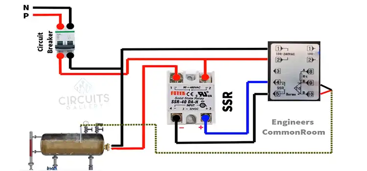
PID SSR Wiring Diagram
The diagram below shows a standard wiring diagram from the PID controller to SSR to load.
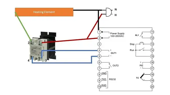
PID Controller Terminal Identification
The PID controller requires specific terminations to acquire power and transmit signals:
- Black: 100-260VAC Power Supply Input
- Red: Power Supply Return
- Blue: SSR Control Signal Output Terminal
- Blue: SSR Feedback Signal Input
State State Relay Terminal Identification
The SSR leverages designated terminals for connectivity:
- Red: 110VAC Load Supply Voltage Input
- Green: Switched Load Output Terminal
- Blue: PID Control Input Signal
- Blue: PID Feedback Output Signal
Load Terminal Identification
The load itself ties into two points:
- Black: Neutral/Return Path Connection
- Red: 110VAC Hot/Supply Power Input
Wiring Connection in PID SSR Wiring Diagram
With the terminals identified, let’s discuss the wiring connections that bring the PID controller, SSR, and load together:
Power Supply Linkage
The PID controller requires an electricity source for functionality:
- Link the controller’s black wire to the AC neutral
- Connect the controller’s red wire to the AC hot wire
- Verify appropriate PID supply voltage rating
This furnishes essential operating power.
PID-to-SSR Signal Routing
With power secured, the PID and SSR must connect:
- Run PID blue output wire to SSR blue input
- Return SSR blue wire back to PID blue input
- Check signals for adequate current/voltage
This crossover passes controlling signals between the components.
SSR AC Power Circuit
The SSR’s switching capacity gets leveraged next:
- Attach SSR red terminal to AC power hot
- Link SSR green output terminal to load end
- Ensure SSR ampacity exceeds load rating
This allows AC runs to activate the load appropriately.
Completing Load Connections
Finally, finish linking the load itself:
- Connect one load-end black wire to a neutral
- Join other load ends red wire to SSR AC hot out
This provides an egress path for actuating current.
Verifying & Testing Circuit Integrity
Before energizing, validate all prior steps thoroughly:
- Confirm tight, secure wire terminal connections
- Check wire sizing applicable to load currents
- Review schematic matching and component layout
- Activate momentarily to verify the proper response
Such diligence prevents any subsequent faults or unreliability.
Additional Monitoring & Control Integration
Consider expanding the fundamental PID-SSR-Load configuration by appending:
- Direct network communication modules
- Master industrial control relays
- Motor starter components
- Alarm annunciators
- Data logging equipment
Supplementary attachments greatly extend functionality.
Special Considerations by Load Type
When specifying components, match SSR switching type to load:
- Resistive Loads: Simple SSRs typically suffice
- Inductive Loads: Employ zero-crossover SSRs
- Lamp Loads: Configure for inrush versus steady-state currents
Appropriate SSR selection prevents false tripping or failure.
Safety Guidance while Wiring
Strictly follow this safety procedures:
- Verify ABSOLUTE de-energization before accessing
- Employ securely insulated wires and connectors
- Route high voltage paths safely away from lower DC
- Test functionality cautiously once powered up
Thorough standards drastically improve safety.
Common Troubleshooting Tips
If facing activation problems:
- Methodically check continuity from power to PID, PID to SSR, SSR to load
- Examine all linkage points for loose connections or shorts
- Inspect supply voltage actually reaching PID and SSR
- Review schematic matching to deployed wiring
- Consider SSR replacement if non-responsive
Meticulous verification resolves most issues.
FAQs – Frequently Asked Questions and Answers
- What is the distinction between a PID controller and an SSR?
Answer: A PID controller is an electronic device that regulates process variables, while an SSR acts as a switch for high-power AC loads. PID controllers often work in conjunction with SSRs to control these loads effectively.
- What is the maximum load current that can be used with an SSR?
Answer: The maximum load current that you can use with an SSR depends on the specific type of SSR and the heat sink. It is crucial to consult the SSR datasheet to determine the maximum load current rating. Exceeding the maximum load current can lead to overheating, damage to the SSR, and potential safety hazards.
- What purpose does the SSR heat sink serve?
Answer: The SSR heat sink serves to dissipate heat generated during the switching process. As the SSR switches on and off, it generates heat, and the heat sink helps to disperse this heat, preventing the SSR from overheating and potentially causing damage.
To Conclude
PID SSR wiring diagrams play a crucial role in establishing control over high-power AC loads in various industrial applications. By understanding the terminal identification, wiring connections, and safety precautions outlined in this comprehensive guide, you can effectively and safely connect PID controllers, SSRs, and loads, ensuring precise regulation and maintaining a safe working environment.
Subscribe to our newsletter
& plug into
the world of circuits