PWM DC Motor Speed Controller Circuit Using PIC16F877A Microcontroller
We have already covered PWM generation using PIC Microcontroller. As I told you earlier PWM has wide applications in electronics and robotics engineering. In this article I’m gonna show you one of the important applications of PWM in Robotics, it is called Pulse Width Modulation motor speed control.
The method of generation of the PWM signal is the same as before and this signal is applied to the Enable terminal of the L293 motor driver IC. L293 is an H bridge motor controller IC capable of driving 2 Motor loads at a time. Below is the detailed description of dc motor speed control.
Why do We Need Pwm for Speed Controlling of DC Motor
You may wonder why we need a PWM signal for controlling DC motor speed when a resistor in series with the motor can simply do this job.
It’s because this method is not recommended in practical and also you don’t get enough torque to drive the motor with the help of a resistor.
Limitations of using a resistor
- DC motor needs more power during the operation, also it draws more current from the supply.
- If we use resistors, the motor will not get enough power to rotate because some of the power is dropped across the resistor (Low current).
- Also the current will be very low.
So, How to control DC motor speed effectively? Here comes the importance of the PWM technique…!
DC Motor Speed Control Using PWM Technique
- With the help of PWM, it is possible to control the average power delivered to a load and thus we can easily regulate the speed of the DC Motor.
- When the width of the pulse is high, the motor will rotate at full speed.
- Obviously, with low pulse width, the speed of the motor gets reduced.
- In both cases full current reaches the motor and only the average power changes, thus we get better torque in each case.
- Basically, in this method, we are chopping the DC voltage at regular intervals.
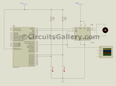
PWM DC Motor Speed Driver Schematic
Pic 16f877a PWM DC Motor Speed Control Mikro C Program
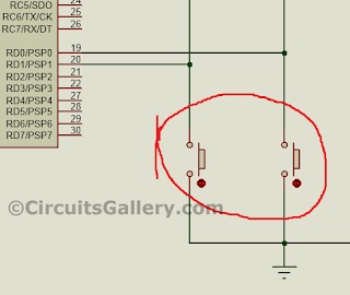
In this Mikro C embedded C program, two input switches are used to control the duty cycle of the PWM signal.
S1 for increasing duty cycle and S2 for decreasing the same.
The frequency of the PWM signal is set to 1 kHz.
| 1 2 3 4 5 6 7 8 9 10 11 12 13 14 15 16 17 18 19 20 21 22 23 24 25 26 27 28 29 | void main() { short duty1 = 16; //initial value for duty TRISD = 0xFF; //PORTD as input TRISC = 0x00; //PORTC as output TRISB = 0x00; //PORTB as output PORTB = 0x02; //Run motor in anticlock wise PWM1_Init(1000); //Initialize PWM1 PWM1_Start(); //start PWM1 PWM1_Set_Duty(duty1); //Set current duty for PWM1 while (1) // endless loop { if (PORTD.F0==0) //Checking the button pressed or not { Delay_ms(1); duty1++; // increment duty cycle PWM1_Set_Duty(duty1); //Change the duty cycle } if (PORTD.F1==0) // Checking the button pressed or not { Delay_ms(1); duty1–; // decrement duty cycle PWM1_Set_Duty(duty1); } Delay_ms(10); } } |
All the program codes are self-explanatory, if you have any doubts please let us know through the comment box below.
Pic Pwm Motor Speed Control Simulation in Proteus 8
Let’s start our virtual lab!
Step 1
Generate .Hex file for PWM speed control in Mikro C.
Compile the above program in Mikro C.
Step 2
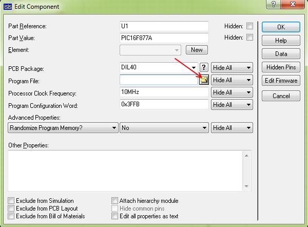
Draw the schematic in Proteus 8 as shown.

Step 3
Load .Hex file to the PIC.
Practical help Use our USB PIC Programmer circuit for burning PIC Microcontroller practically.
Step 4
Now Run the simulation.

Step 5
Change the duty cycle using provided keys and observe the speed of the DC motor (watch the video).
Subscribe to our newsletter
& plug into
the world of circuits

![Which Amplifier Is Best Transistor or MOSFET? [Compared and Explained]](https://www.circuitsgallery.com/wp-content/uploads/2023/07/which-amplifier-is-best-transistor-or-mosfet.webp)