What Is Zero Voltage From Op-Amp | Explained and Its Significance?
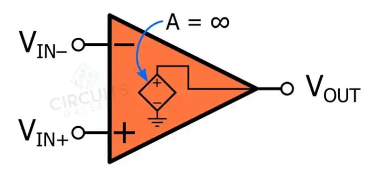
Zero voltage from an op-amp refers to the condition where the output voltage of the op-amp is zero when there is no input voltage applied for an ideal op-amp. However, in practical op-amps, the output voltage deviates slightly from zero, resulting in a small offset voltage due to imperfections in their internal circuitry.
This offset voltage can introduce errors in amplification and affect the overall performance of op-amp circuits. Techniques such as offset nulling are employed to minimize the offset voltage and bring the output closer to zero.
What Makes the Output Voltage Equal to Zero in Practical Op-Amps?
As mentioned before, the output voltage is not precisely zero when there is no input voltage difference in practical op-amps. Output offset voltage can cause inaccuracies in amplification and introduce errors in various applications. Techniques such as offset nulling are employed to minimize this offset voltage and bring the output closer to zero.
In offset nulling, an external resistor or potentiometer is connected to the offset null pins of the op-amp. By carefully adjusting the resistance value, the offset voltage can be minimized or eliminated.
What is Zero Offset Voltage in Op-Amps?
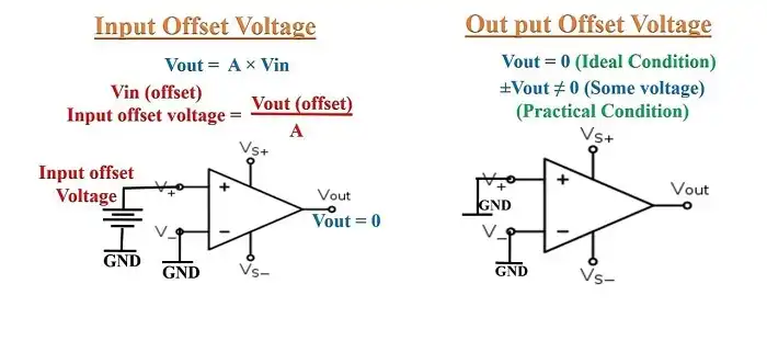
Figure: Offset Voltage of Op-Amp
Input offset voltage or zero offset voltage is a quite crucial parameter in op-amps. It refers to the voltage that must be applied to the input terminals of an op-amp to nullify its output voltage when there is no differential input voltage present.
For an ideal op-amp, the input offset voltage is zero. However, in practical op-amps, it is a small voltage that can lead to output errors and affect circuit performance.
What is Op-Amp Dropout Voltage?
Op-amp dropout voltage is the minimum voltage required between the power supply rails for the op-amp to operate correctly. When the input or output voltage approaches the power supply rails, there might be a reduction in its gain or failure to function altogether.
Dropout voltage is a critical specification to consider when designing circuits that operate near the supply voltage limits, ensuring reliable and accurate performance of the op-amp.
Why does an op-amp have zero output impedance?
The output impedance of an op-amp is designed to be very low and ideally zero. Low output impedance ensures a significant voltage drop, allowing the op-amp to deliver a stable output voltage to different loads.
To Conclude
Even though ideal op-amps exhibit zero voltage behaviors, practical op-amps deviate from this characteristic for various factors. Make sure to consider the impact of zero voltage conditions and employ appropriate techniques to optimize op-amp performance and enhance the reliability of the overall system.
Subscribe to our newsletter
& plug into
the world of circuits

![Does Super Glue Conduct Electricity [Explained]](https://www.circuitsgallery.com/wp-content/uploads/2023/12/Does-Super-Glue-Conduct-Electricity.webp)
![[Explained] What Happens if the Live and Neutral Wires Are Swapped?](https://www.circuitsgallery.com/wp-content/uploads/2023/10/What-Happens-if-the-Live-and-Neutral-Wires-Are-Swapped.webp)