What is the Resonance Frequency if the Resistor Value is Doubled? [Mathematically Explained]
The resonance frequency is unaffected by doubling the resistor value alone. The resonance frequency, however, can be altered if the complete circuit is altered, such as by altering the inductor or capacitor values.
The inductance and capacitance components of a circuit define the resonance frequency of that circuit. Though the resistor plays a part in dampening the circuit and lowering the quality factor, it doesn’t directly affect the resonance frequency.
What will happen to the Resonance Frequency if the Resistor Value is Doubled?
When the reactance of the inductor and capacitor cancel each other out and leave only a resistive impedance, resonance happens in an electrical circuit. The resonance frequency of a simple RLC circuit, which consists of a resistor, an inductor, and a capacitor connected in series or parallel, is given by the formula:
f = 1 / (2π√(LC))
where,
f is the resonance frequency in hertz (Hz),
L is the inductance in Henries (H),
C is the capacitance in farads (F), and
π is a mathematical constant approximately equal to 3.1416.
From the equation, it can be seen that there’s no term for the resistor. That means the resonance frequency is independent of the resistance. It doesn’t matter if the resistance is doubled or halved, the actual resonance frequency will be the same until the inductance or capacitance is changed.
How Does Resistor Affect Resonant Frequency?
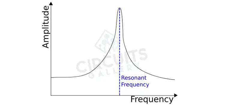
From the equation of the resonance frequency, it is seen that the frequency doesn’t depend on the value of the resistance. So, as previously established, the resistor (R) doesn’t affect the resonance frequency. However, by impacting the circuit’s damping and the quality factor (Q), it influences the contour and characteristics of the resonance curve.
The following formula is used to determine the Q factor,
Q = 1 / R√(LC)
The Q factor of the circuit is reduced by doubling the value of the resistor (R). As a result, the resonance peak broadens and loses some of its sharpness, and energy dissipates more quickly.
On the other hand, if the resistance is cut in half, the Q factor rises and the resonance peak becomes sharper and more apparent. As a result, there will be more energy held in the circuit for a longer duration, increasing the resonance frequency’s amplitude.
What is the Value of Resistance at Resonance Frequency?
At the resonance frequency of a series RLC circuit, the resistance (R) has a certain relationship with the inductance (L) and capacitance (C) in the circuit. The stated formula for the resonance frequency (fr) is, fr = 1 / (2π√(LC))
As already mentioned, during resonance, the reactances of the capacitor (XC) and the inductor (XL) cancel one another out, leaving only a resistive impedance. This occurs when XL = XC.
The reactance of an inductor is given by, XL = 2πfL
And the reactance of a capacitor is given by, XC = 1 / (2πfC)
Since, XL = XC, we have, 2πfL = 1 / (2πfC)
Simplifying further:
2πfL = 1 / (2πfC)
f^2 = 1 / (4π^2LC)
Substituting the resonance frequency (fr) into the formula:
fr^2 = 1 / (4π^2LC)
Rearranging the equation to solve for R,
R = √(L / C) / (2πf)
So, the resistance (R) at the resonance frequency is, R = √(L / C) / (2πfr)
In a series RLC circuit, this formula demonstrates the relationship between resistance, inductance, capacitance, and resonance frequency. By specifying the values of inductance, capacitance, and resonance frequency, we can get the value of the resistance in the circuit at the resonance frequency.
Conclusion
At resonance, the circuit displays specific properties such as maximum current or minimum impedance, depending on the setup. However, resistance is not the value to consider while determining the resonance frequency. Anything done with the resistor value doesn’t directly affect the resonance frequency value but only the resonance’s characteristics and shape.
Subscribe to our newsletter
& plug into
the world of circuits
![[Explained] Do Amps Come With Cables?](https://www.circuitsgallery.com/wp-content/uploads/2023/12/Do-Amps-Come-With-Cables.webp)
![Can A Bad Breaker Cause Low Voltage [Answered]](https://www.circuitsgallery.com/wp-content/uploads/2023/09/Can-A-Bad-Breaker-Cause-Low-Voltage.webp)