Does a Resistor Reduce Voltage | Explained for Both AC and DC
The resistor causes a voltage drop by delaying or resisting, electrons as they try to flow through it. A component that receives too much voltage may be damaged or fail to perform properly. So, yes, the resistor does reduce voltage.
The voltage across a resistor is known as voltage drop, and its magnitude is proportional to the resistance value. The larger the resistance value, the greater the voltage drop across that resistor. The voltage across each resistor can be calculated using Ohm’s law: V=IR.
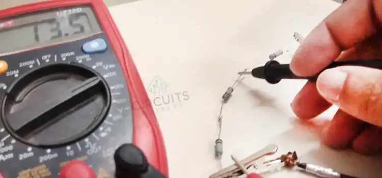
How Does a Resistor Affect Voltage
The effect on voltage is quite different, though similar in some aspects, in DC and AC circuits. DC circuits simply follow Ohm’s law. But, it is the phase relationship between voltage and current that determines the voltage drop in case of AC circuits.
In DC Circuits
A resistor regulates the passage of electrical current in a circuit. Resistors, which are constructed of materials such as copper or carbon, make it difficult for electrical charges to flow across a circuit. Hence there exists a voltage drop across the resistor.
From Ohm’s law, V=IR.
Where:
- V is the voltage drop across the component (in volts, V).
- I is the current flowing through the component (in amperes, A).
- R is the resistance of the component (in ohms, Ω).
Hence voltage drop is directly proportional to both resistance and current.
In AC Circuits
As the value of both voltage and current fluctuates in AC circuits, the resistor experiences a flow of electrons to and fro between the terminals. This is entirely different than what happens in DC circuits. To make it simple and analogous to DC circuits, V and I are taken as Root Mean Square (RMS) values.
Ohm’s law is simply maintained only if the load is a (or a combination of ) resistor(s). But in other cases where other passive elements such as inductors, and capacitors are present, the voltage reduction depends on the impedance. In such cases, the voltage drop isn’t simply proportional.
Why Does Voltage Drop After a Resistor?
Electrons lose energy as they interact with electrons in the conducting substance as they pass through a resistance. As energy is given up by the material, it accumulates thermal energy and thus rises in temperature. Moving electrons lose potential energy, resulting in a voltage drop.
Conclusion
A resistor will provide a voltage drop to guarantee that a component in your circuit does not receive too much electricity if it requires less voltage than the remainder of your circuit. If the voltage remains constant but the resistance increases, the current measured through the component would also increase.
Subscribe to our newsletter
& plug into
the world of circuits
