Measuring Inductance With Oscilloscope | A Step by Step Guide
To measure inductance with an oscilloscope, you can use three frequent methods. The first one is the resonant frequency method, the second one involves using a resistor of known value and the third one is by using voltage-current slope.
Inductances are measured in Henries. A current-carrying coil tends to oppose the change in current flowing through it. Simply, inductance opposes any instantaneous change in current.
Methods to Measure Inductance With Oscilloscope
The self-inductance of a coil is expressed as L. Coils induce EMF whenever the current(i) flowing through it changes. This induced EMF(V) is proportional to the current change rate (di/dt). Hence, E ∝ di/dt. Again, E=L*(di/dt). Here, L is inductance. It’s the ratio of the induced voltage to the rate of change of current.
According to Lenz’s law, the direction of this induced EMF is such that it opposes the change of current for which the EMF was generated in the first place. You must know the right value of inductance to design circuits. The ways to measure inductance with oscilloscopes are discussed below.
Method-1: Resonant Frequency Method
For this method you’ll need:
- Oscilloscope.
- Diode.
- Inductor
- A capacitor of a known value.
- A resistor of a known value.
- Function generator.
- Calculator.
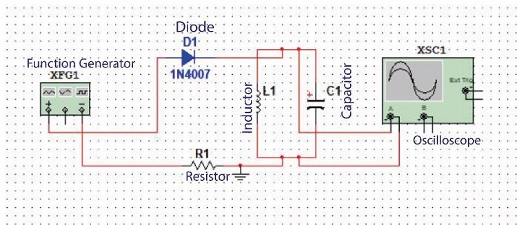
Step-1: Connect the instruments as the following figure:
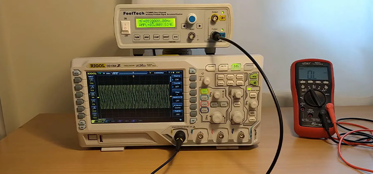
Step-2: Give power to your function generator and scope.
Step-3: Set the scope probe to 10x.
Step-4: Keep increasing the frequency of your function generator until you notice the resonance frequency on your oscilloscope.
Step-5: Now measure the value of your inductance(L) from the following equation:
Resonance frequency, f = 1/(2π√(LC))
Method-2: Using a resistor of known value
The instruments required for this method are:
- Oscilloscope.
- Function generator.
- Inductor.
- Resistance of known value(100Ω).
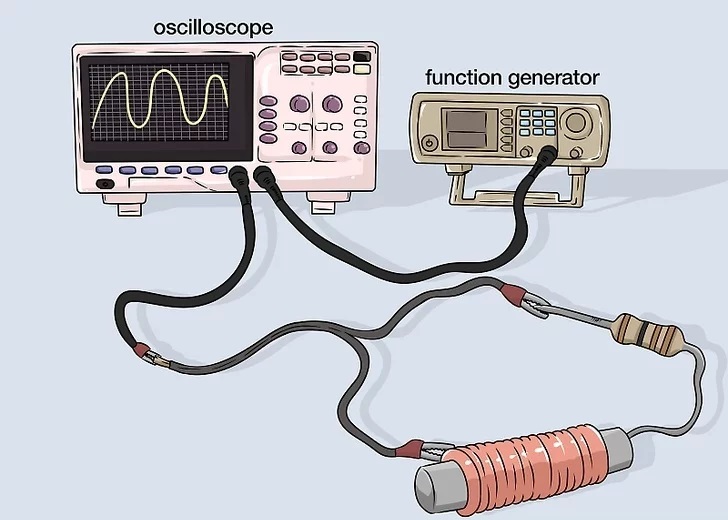
Step-1: Connect the instruments as the following figure:
Step-2: Give power to your function generator.
Step-3: Note the frequency from the function generator for a specific voltage. Suppose the frequency will be 10.01 kHz for 1V.
Step-3: Now adjust the frequency so that the voltage becomes half of that specific voltage. Suppose the frequency will be 20kHz.
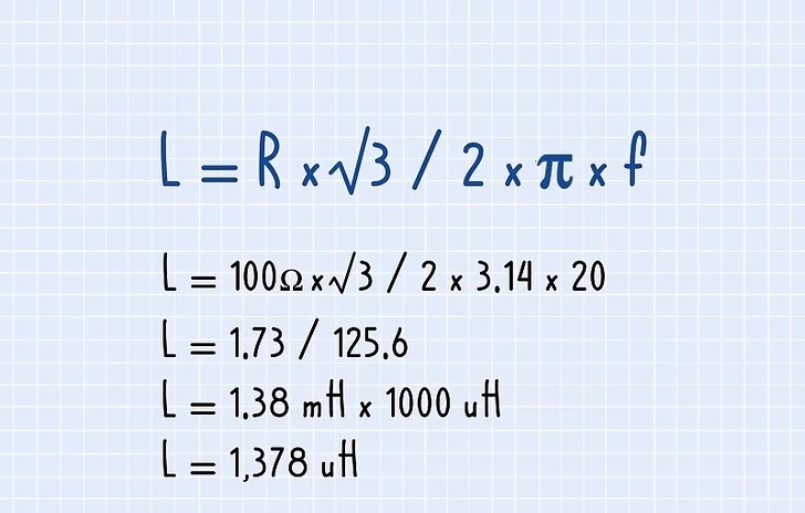
Step-4: Now perform the following calculations to find your inductance:
Method-3: Using Voltage-current Slope
Step-1: Connect your inductor to a pulsed voltage source. The duty cycle of the source must be 50%.
Step-2: Read the peak current and the time between pulses from your oscilloscope.
Step-3: Determine the difference of current magnitude(di) for a specific time interval(dt) from your oscilloscope. Now calculate di/dt.
Step-4: Note the voltage(V) and calculate V/(di/dt). This is your required inductance.
Steps for Measuring Inductance With a Multimeter
There isn’t any direct way to measure the inductance with a multimeter. But you can check the continuity of your inductor by using a multimeter. To measure inductance with a multimeter, perform the following steps:
Step-1: Measure the resistance(r) of your inductor.
Step-2: Connect the circuit like the following figure. Use a resistor(R) of known value.
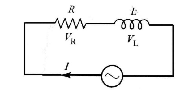
Step-3: Set the frequency between 2kHz to 10kHz.
Step-4: Note the voltage of the resistor(R) using the multimeter. Mark the voltage as ‘x’.
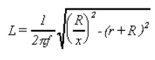
Step-5: Use the following relation of the figure to find inductance, L:
How Do You Measure Inductance of a Coil?
As you’ve seen multimeters can’t directly measure the inductance of a coil. To directly measure it, you need an LCR meter.
The inductance of a coil depends on the magnetic flux around it. The magnetic flux arises due to the flow of current through the conductor. LCR meters are digital multimeters. LCR meters measure the impedance of the inductor and display the inductance.
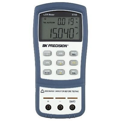
Figure- LCR Meter
What Instrument Measures Inductance?
There are various instruments out there to measure the inductance of your inductor. The most frequently used ones are given below:
- Oscilloscope.
- LCR meters.
- Frequency counter.
- Inductance meter.
Uses of Inductors
Inductors are widely used as energy storage devices. These devices are widely used in tuning circuits, transformers, inductive sensors, induction motors, etc. Assuming the importance of inductors, the measurement of inductance is mandatory.
Conclusion
Inductors are used everywhere. As multimeters can’t measure inductors directly, you need oscilloscopes or other instruments to measure inductance. Oscilloscopes are electronic test instruments to see the graphical image of any varying voltages. These instruments are easy to use.
Subscribe to our newsletter
& plug into
the world of circuits