How to Tell If Ceiling Fan is Single or Dual Capacitor? | Find Out with the Help of Microfarad Rating
One can tell that the ceiling fan has a single capacitor if there is a single microfarad rating. If there are two, then it has a dual capacitor. Another way is to check the wiring terminals. If there are two sets of terminals, then it is a single capacitor. If there are three, then it is a dual capacitor.
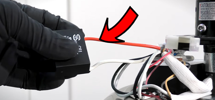
How Do You Find out If the Ceiling Fan Is a Single or Dual Capacitor?
There are two ways to tell if your ceiling fan has a single or dual capacitor. The first one is to look at the micro Faraday rating on the capacitors. The micro Faraday rating is usually designated by μF or MFD.
If there is only a single micro Faraday rating, it is a single capacitor. However, if there are two micro Faraday ratings on the capacitor, then it is a dual capacitor.
Another way to tell apart your ceiling fan’s capacitor is by just looking at the wiring terminals of the capacitor. In a single capacitor, there are two sets of terminals on top. Whereas, in a dual capacitor, you will see three sets of wiring terminals. The dual capacitor is basically two capacitors in one package.
What is the Difference Between a Single and Dual Capacitor?
There are major differences between a single and a dual capacitor. A single unit run capacitor connects to a single motor. Normally, it is used in smaller HVAC systems such as small air conditioners.
On the other hand, a dual capacitor utilizes two capacitors in one unit. This two-in-one package offers power to two electric motors. This makes it ideal for larger HVAC systems such as large air conditioners and heat pumps.
How Many Capacitors Should a Ceiling Fan Have?
Typically in a ceiling fan, two capacitors in parallel series are used. The capacitor starts the fan and makes it spin as well. It does so by generating a magnetic field that rotates the fan.
Why Does My Ceiling Fan Have Two Capacitors?
A ceiling fan normally has a single-phase induction motor in it. According to its principle, the engine does not start by itself. Therefore, an external force is required to overcome this shortcoming.
This is where a capacitor comes from. It creates a magnetic flux that rotates the fan. Typically, you will see two capacitors in parallel series in your ceiling fan.
The one with high capacitance is connected to the starting winding of the split-phase induction motor. The other one with low capacitance is connected to the running winding. This is why your ceiling fan has two capacitors.
Which Capacitor is Used in Ceiling Fan?
In a ceiling fan, a non-polarized electrolytic AC capacitor is used normally. The capacitor has a value of around 2.2 MFD or 250 V used for the ceiling fan motor.
Conclusion
One thing you have to keep in mind is that if you connect the capacitor in series with the main winding, the fan blades will rotate in the opposite direction. With the help of this article, you can now easily identify the capacitor in your ceiling fan.
Subscribe to our newsletter
& plug into
the world of circuits