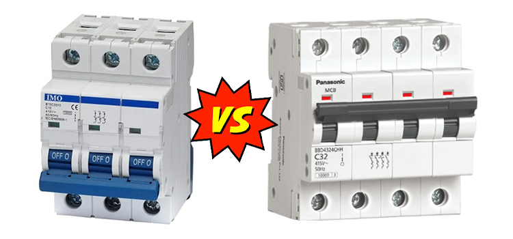
3 Pole vs 4 Pole | Differences Between 3 & 4 Pole Isolator
A 3-pole isolator is a no-load switch that isolates only three phases, whereas a 4-pole isolator isolates three phases and the neutral of a three-phase line. 4-pole rotary isolator switch disconnector for commercial and light industrial applications. To prevent opening in the on state, the switch is interlocked with the lid.
The number of distinct circuits that a switch may control is referred to as its pole. A single pole switch can only control one circuit, whereas a double pole switch can control two. As a result, a double pole switch is equivalent to having two single pole switches operated by the same switch.
Comparison between 3 Pole & 4 Pole Isolator
The neutral is constant throughout the system when employing a 3-pole ATS. This is known as a solid neutral, and it is only bonded to the ground at the facility’s utility service entry. Because each source’s neutral is linked to ground at its source in 4-pole ATS systems, each source is termed “separately derived”.
While many factors influence whether to employ a 3-pole or 4-pole switch, it should be noted that in systems with several ATSs, it is critical to choose one of the neutral switching schemes. All transfer switches supporting three-phase, four-wire loads should be of the same type—either all three-pole or all four-pole.
What Does 3-Pole Mean in Electrical Terms
3-pole indicates that the device plug is earthed and includes three pins, two of which are used to transport current and one for personal protection. It is critical to note that removing the ground connection is always dangerous because there is no longer any protection against electric shock.
This earth connection has been built as a leading connection in all 3-pole plugs that correspond to the standards. It shuts the contact before the other two pins make power contact.
What Does 4-Pole Mean in Electrical Terms
4-poles are for 4-wires connections. The one additional 4th pole is for connection between the neutral wire and any of the other three. In 4-Pole MCCBs the neutral pole is also having protective release as in the phase poles.
Lighting can be controlled from three or more locations using four-pole switches. Four-pole switches are used in tandem with three-pole switches. A 4-pole switch has four terminals that offer two sets of toggle positions. Each terminal group represents one of the toggle positions.
What Is the Difference Between 3 and 4 Pole Isolator?
A 3-pole isolator is a no-load switch that isolates only three phases, whereas a 4-pole isolator isolates three phases and the neutral of a three-phase line. So, 3-pole stands for three open, and 4-pole is the N representation of the zero terminal, which is the addition of a terminal based on the three openings.
Normally, in a three-phase system with a neutral, we use a three-pole CB with the neutral connected to a common neutral link. But if using a three-pole CB interferes with the operation of the protective relay, we must use a four-pole CB.
When Should You Use a 3-Pole Breaker
A 3-pole breaker links three distinct conductors, as it’s frequently required by large-duty industrial motors. When a surge crosses one or more conductors in the system, the breaker trips, the power bridge collapses, and the circuit opens. So, 3-pole breakers are used most often in a three-phase electrical system.
Generally, a three-phase electrical supply is used in factories, workshops, and commercial buildings. Three pole circuit breakers provide 480 VAC through three hot wires. As a result, the breaker requires three distinct switches that will cooperate when needed.
What Are 4 Pole Breakers Used For
Isolating the two Neutrals is a required practice. When the system has two alternative sources and, in the event of a power failure from the mains, the standby generator is switched on. So, we can use 4-pole breakers or TPN breakers. It is best practice in such cases to separate the neutral as well.
What Is the Use of 3 Pole Contactor
In most commercial applications, three pole contactors are employed. Three wires are used to control the direction of the electrical current in these contactors. A three-phase contactor controls the power to a three-phase load.
When the voltage needs of the load exceed the power-handling capability of a mechanical relay, you must use 3-pole contactors. However, 3-pole contactors are typically beefier than 2-pole contactors. It’s because they are for three-phase applications, which are typically commercial equipment.
What Is the Use of 4 Pole Contactor
A 4-pole contactor is mostly used to manage non-inductive or mildly inductive loads (such as resistance furnaces), as well as power circuits up to 690 V AC and 440 V DC. These contactors have a block design with four primary poles.
The most common application of a 4-pole contactor is in the starter, which is used to turn on and off equipment such as a motor or a transformer. A contactor, like a relay but with higher current ratings, is an electrically controlled switch used to switch a power circuit.
Frequently Asked Questions
Why is the neutral wire hot?
If the neutral is broken at any place between the light bulb and the panel, the neutral from the light to the point where the neutral is broken will become hot. And the device will be unpowered because no current will be flowing through it.
Conclusion
When using several generators and paralleling switchgear, you should follow the rules for selecting a 3-pole vs. a 4-pole switch. If the emergency power supply is obtained from a separate source, you must install a neutral-to-ground link at each generator or in the paralleling switchgear. Always work with a reputable source.
Subscribe to our newsletter
& plug into
the world of circuits