Fan Center Wiring Diagram | A Simplified Wiring Diagram for Easy Installation and Maintenance
A relay, transformer, and terminal strip for the thermostat wiring that was run from the thermostat to the fan center control terminal strip make up the fan center. The fan center control is often mounted on a 4″ × 4″ junction box within the furnace. The wiring just requires some simple steps.
Fan Center Wiring Diagram
To wire a fan control center electrical power to heating and cooling systems should be turned off. Note the locations and lead colors on the current relay’s leads. Record every exterior wire connection as well.
Duplicate the wiring of the previous control using the colored terminal leads installed on the new fan control center. Ensure that each relay’s connecting points are identical.
How Do You Wire a Fan Center?
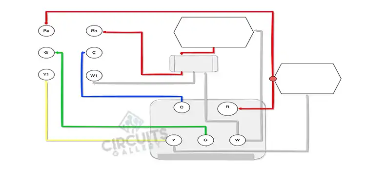
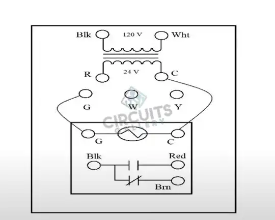
The relays in a fan center are placed on the bottom. Then there is a transformer and a terminal board. The terminal board always has two wires that are pre-wired on it. You will see a C and a wire coming off the G. That actually goes to the coil of the relay. To wire a fan center, keep in mind that 120 volts are applied to the primary side of the transformer.
The thermostat wires are wired directly to the terminal board of the transformer. The terminal ‘C’ and ‘G’ power up the coil on the relay. The wires from your fan connect to the terminals on the relay, whether they are normally open or normally closed.
What Is the Purpose of Fan Center?
The fan control center can be used to manage two-speed blower motors and auxiliary circuits in heating or cooling equipment. It also offers low voltage control of line voltage circuits.
How Do You Wire an AC Fan Relay?
Look at the bottom of the relay, you’ll notice four pins and there are four numbers. Usually, 87 (red wire) joins to the positive wire on the electric fan, 30 (other red wire) requires fixed 12-volt power from the battery, 86 (gray/white wire) goes to the ignition switch and 85 (black wire) joins to the temperature-controlled sending unit.
The electric fan’s positive wire should be connected to one of the two red wires on your relay, while the negative wire needs to be grounded. Find the wiring diagram provided by the fan manufacturer if you are unsure which wire comes out of the electric fan.
If you’re still unsure, wait until the car has reached operating temperature before turning on the fan. If it pulls air from the front of the car, you’ll be able to feel it when the fan turns on. If it’s not, switch the two wires, turn the car off, and you ought to be good to go.
How Do You Wire a Furnace Fan Switch?
This furnace combination control is installed so that the bimetallic spring/probe will extend into the warm air plenum and measure the temperature of the furnace air there. By connecting only the control’s limit terminals, this control can be wired to act as a safety LIMIT switch on a furnace.
All four connections are needed when the device is used as both a LIMIT switch and to turn on and off a furnace fan. The two fan terminals are located on the upper and lower left sides of the control.
Keep in mind that any wiring for furnace controls must adhere to national and local electrical codes as well as the requirements of the control maker and the manufacturer of the furnace. Push-in terminals are employed to join the control’s wires. On the left side of several variations of this control is a wire strip gauge.
Conclusion
Fan centers are very useful to provide low voltage control. You can do the wiring by yourself if you know it well. However, if not, you can seek help from a professional. After completing the wiring, energize the system and check for proper operation.
Subscribe to our newsletter
& plug into
the world of circuits