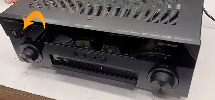
Yamaha Receiver Blinking Red Light | How to Fix?
Yamaha receivers allow you to control audio over many speakers by utilizing channel audio options. They also boost that sound, and even do single-room correction on the signal, all of which increase sound quality.
A problem in your Yamaha receiver circuit causes the red light to blink. A problem with the speaker wiring between the receiver and speakers can cause your equipment to blink the red light. Now let’s dig deeper.
Why is My Yamaha Receiver Blinking a Red Light?
The reasons why your Yamaha receiver is blinking e red light are illustrated below with their respective solutions.
1. Power Surge
A power surge is a spike in voltage that can harm electronic devices. When a power surge happens, it can send a spike of voltage through the receiver, damaging the internal components. If your receiver has been subjected to a power spike, it may fail to function properly or at all.
Solution
Always use a surge protector to protect your receiver from power surges. A surge protector is a device that absorbs excess energy from a power surge, keeping your electrical gadgets safe. When selecting a surge protector, be sure it has a high enough joule rating to protect your receiver.
2. Blown Fuse
In most cases, a blown fuse in a Yamaha receiver indicates a problem with the receiver’s power supply. It may cause the red light to blink.
Solution
To replace the blown fuse, you must detach the Yamaha HS5 and access your receiver. It would be ideal if the fuse mount was made in the same way as KRK monitors, with the user just unplugging the plastic mount under the power connection to replace the fuse.
A screwdriver, pliers (needle nose), and a new T400mAL250V slow blow glass fuse are required.
3. Short Circuit
A short circuit in a Yamaha receiver is a condition in which an electrical connection is made between two locations that should not be connected. This can be caused by a variety of circumstances, including a broken component, a loose connection, or physical damage to the receiver.
Solution
To avoid short circuits in your Yamaha receiver, you should do the following:
- Disconnect the mains, remove the amplifier top cover
- Locate the IC82, a small 8-pin EEPROM near the main processor, jumper pins 2 and 3 with a small screwdriver, and reconnect the main power wire.
- The receiver should be reset and turned on. You may need to press the power button at times.
- After it turns on, simply remove the jumper and you’re done.
4. Faulty Component
A Yamaha receiver can have a variety of malfunctioning components. Some of the most common defective components are as follows:
- Power supply
- Transistors
- Resistors
- Diodes
- Capacitors
Solution
Here are some more hints for identifying a defective component in a Yamaha receiver:
- For details on the placement of the components, consult the owner’s manual for your individual model of receiver.
- Measure the voltage, current, and resistance of the components using a multimeter.
- Look for tangible indicators of damage, such as cracks, burns, or discoloration.
- If you are not confident in analyzing and fixing a problematic component in your Yamaha receiver, you should seek the assistance of a competent expert.
5. Software Glitch
Yamaha receivers can occasionally suffer from software issues. These flaws can lead to a range of issues, including:
- The receiver will not turn on.
- The receiver is not producing any sound or image.
- Error messages are displayed by the receiver.
- Commands are not being received by the receiver.
- The receiver is acting strangely.
Solution
If you believe your Yamaha receiver is having a software glitch, you can try the following fixes:
- Restart the receiver
- Update the receiver’s firmware
- Factory reset the receiver
Frequently Asked Questions and Answers – FAQs
How Can I Reset My Yamaha Receiver if It’s Blinking a Red Light?
Keep in mind, however, that you will lose all existing settings. To reset your Yamaha receiver perform the following steps:
Step 1: Ensure that it is plugged in.
Step 2: Next, click the “info” and “tone control” buttons all at once. Hold down the button for a few seconds.
Step 3: Finally, the receiver will turn on and a “clicking” sound will be heard.
How Can I Prevent My Yamaha Receiver From Overheating and Triggering the Red Light
When you’re stumped as to why your receiver keeps heating up, try this easy remedy.
Step 1: If your receiver overheats, simply turn it off.
Step 2: Deactivate the Wi-Fi connectivity choices as well.
Step 3: Carefully place it in a separate spot with plenty of space all around. Particularly on the top and sides.
Step 4: Let it cool down.
Step 5: Turn on the computer and check to see if the tendency for overheating is still present.
Why Does My Receiver Keep Going Into Protection Mode?
If any of the speakers’ impedance falls below the rated impedance range shown on the rear of the home audio device adjacent to the speaker connections, the home audio device may enter protection mode. Raise the volume on a low-impedance speaker to activate the protective circuit.
Conclusion
In general, the red blinking indicates “protect” mode. It unravels the reasons behind this predicament, from power surges to blown fuses, short circuits, faulty components, and software glitches. When a fault is discovered, the equipment shuts down to prevent further harm to either the receiver or the speakers.
Subscribe to our newsletter
& plug into
the world of circuits