What Is the Difference Between Differential Gain and Common-Mode Gain? | A Detailed Comparison between Two Input Signals
The key difference between differential gain and common-mode gain is that differential gain refers to the gain applied to the difference between two input signals in a differential amplifier whereas Common-mode gain refers to the gain applied to signals that are common to both inputs.
The following sections will shed more light on the differences.
Differences between Differential Gain and Common-mode Gain
The primary differences between Differential Gain and Common-mode Gain are as follows:
1. Configuration
Differential Amplifier Configuration
Differential amplifier configuration is an arrangement where the voltage difference between inverting and non-inverting terminals is amplified.
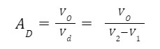
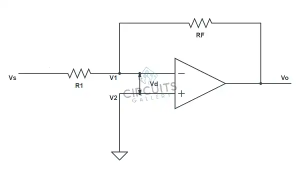
Fig. Differential Amplifier Configuration.
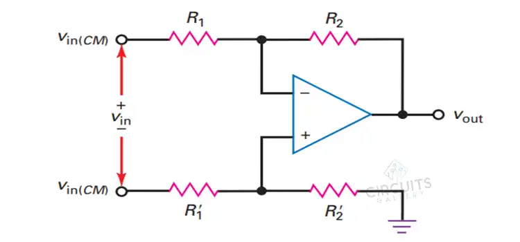
Common-Mode Configuration
An op-amp is said to be operating in a common-mode configuration when the same input voltage is applied to both inverting and non-inverting terminals of the op-amp.
Ideally, no common-mode output voltage appears in the output because op-amp amplifies only differential input voltage. However, due to imperfections in op-amp, very small and often insignificant common-mode output voltage appears. Therefore, the ratio of this common-mode output voltage and input voltage is called common-mode voltage gain.
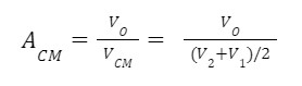
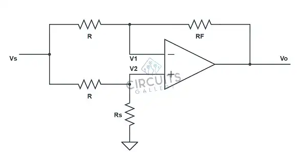
Fig. Common-mode Configuration.
2. Typical Value
Generally, the value of differential gain is very high ranging from 100,000 to 1 million. For an ideal op-amp, it is infinite.
But the common-mode gain is much smaller than 1, ideally zero.
3. Effect on Noise
Differential Gain amplifies noise. On the other hand, the common mode rejects Noise.
4. Application
Differential Gain is important for accurate signal analysis, measuring small signals in the presence of noise and amplifying small signals with noise. Common-mode gain is important for isolating signals from common noise and interference reduction.
5. Implication for Circuit Design
Differential Gain can be increased by changing resistor ratios. However, Common-mode gain can be reduced by increasing resistor precision.
6. Relationship to Input impedance
Differential gain is affected by source and amplifier impedance whereas Common-mode gain is largely independent of the input impedance.
7. Behavior in Different Circuit Configuration
Differential gain varies with non-inverting vs inverting modes. Meanwhile, Common-mode gain is consistent across configurations
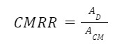
8. Relationship to CMRR
Common Mode Rejection Rate is defined as the ratio of the differential gain to the common-mode gain.
Frequently Asked Questions (FAQs)
Does All Amplifier Have Differential and Common-Mode Gain?
Answer: Yes. Most amplifiers exhibit both gains to some extent. However, the balance of these gains can vary depending on the amplifier’s design and intended application.
What Specific Application Emphasizes One Gain Over the Other?
Answer: For applications demanding signal fidelity, differential gain is emphasized. For noise-sensitive scenarios, common-mode gain takes precedence.
Can Differential and Common-Mode Gains Be Adjusted Separately in Amplifiers?
Answer: In some cases, amplifier gains can be adjusted separately. However, amplifiers often have inherent value for these gains based on design.
To conclude
Understanding the difference between differential and common-mode gain is crucial in signal processing. The differential gain is desirable since it amplifies the meaningful signal, while the common-mode gain is undesired as it only amplifies the noise. The overall aim is to keep the differential gain high and the common-mode gain low for optimum signal processing.
Subscribe to our newsletter
& plug into
the world of circuits