[Explained] 
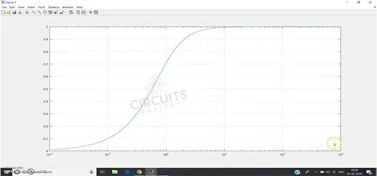
What Is the Objective of High Pass Filter Experiment?
The high-pass filter experiment is one of the most important experiments as well as learning experiences for students of electrical and electronic engineering. Other related fields also has the same where signal processing is concerned.
The main objectives of the High-Pass Filter experiment are to:
- Understand the working principle of a high-pass filter.
- Build a high-pass filter, and measure its frequency response
- Analyse the filter’s attenuation and phase shift characteristics

High-Pass Filter | The Circuitry
A high-pass filter is a circuit that allows signals with frequencies above a certain cutoff frequency to pass and attenuate signals with frequencies below the cutoff frequency.

Fig. High-Pass Filter.
Discussion On The Objectives Of High Pass Filter Experiment
Objectives of High-pass Filter are explained below:
1. Working Principle
In an RC circuit configured as a high-pass filter, the capacitor acts as a frequency-dependent impedance that blocks low frequencies and passes high frequencies.
At low frequencies below the cutoff frequency (fc), the capacitor impedance is very high. This is because the capacitor’s impedance is inversely proportional to frequency.
Since the capacitor’s impedance is so high at low frequencies, it essentially acts as an open circuit to the low-frequency signals. This prevents the low-frequency current from flowing through the capacitor. As a result, the low-frequency signals are forced to flow through the resistor instead. This forms a voltage divider with the resistor, attenuating the low-frequency voltage.
2. Frequency Response
A sine wave input signal is applied to the high pass filter at various frequencies higher and lower than the cutoff frequency fc. The output magnitude (gain) and phase shift are measured at each input frequency using an oscilloscope, spectrum analyzer, or network analyzer. The gain is calculated in decibels using the formula:

Fig. Gain Response of a High Pass Filter.
The phase shift is calculated in degrees using the formula:

Fig. Phase Shift Response of a High Pass Filter.
The Gain plot and phase plots provide the complete frequency response of the high pass filter.
3. Analyse Filter Attenuation and Phase Shift Characteristics
At least four of the following characteristic aspects should be important while conducting the experiment.
Cut-off frequency
The cut-off frequency is determined by finding the frequency at which the output amplitude has dropped by 3dB (0.707 of the maximum). Using the following formula cut-off frequency is calculated:
Roll-off Rate
The roll-off rate specifies how rapidly the filter attenuation increases below the cut-off frequency, fc. It is usually expressed in dB/octave or dB/decade. The first-order high pass filter has a roll-off rate of -6 dB/octave or -20 dB/decade. Higher order filters have faster roll-off rates, such as -12 dB/octave for a 2nd order filter.
Stopband Attenuation
The stopband is the band of frequencies below the cutoff frequency which the filter attenuates. Stopband attenuation is the amount of attenuation applied to the stopband frequencies.
Passband Ripple
The passband is the band of frequencies above the cut-off frequency, fc that passes through the filter. Passband ripple refers to variations in the filter’s gain as frequency increases in the passband.
Frequently Asked Questions (FAQs)
1. What Are the Real-World Factors That Affect Filter Performance?
Answer: Non-ideal components such as parasitic elements, temperature variation, device nonlinearities, and manufacturing tolerances can all degrade stopband attenuation, passband ripple, phase response, and roll-off sharpness.
2. How to Improve the Sharpness of the Cutoff Frequency?
Answer: Cascading multiple high-pass filter stages increases the order and produces a sharper roll-off near the cutoff frequency. Higher orders have faster roll-off rates.
3. What Instruments Are Typically Used to Measure Frequency Response?
Answer: Network analyzer, spectrum analyzer, and function generators with oscilloscopes are commonly used. Automated filter test setups are also employed.
To conclude
This experiment explains filter behavior, evaluates its application, and identifies issues for troubleshooting. It helps in designing the high pass filters to meet real-world needs. Mastering frequency response methods is a fundamental skill for engineers to create robust, effective filter design.
Subscribe to our newsletter
& plug into
the world of circuits