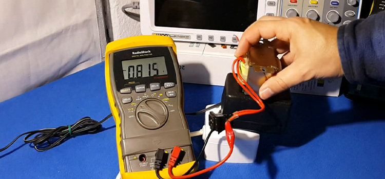
You can use an ohmmeter or multimeter to check a transformer. Simply connect directly the red and black pins of your ohmmeter to the different ends of the transformer’s wiring to test it. To check the transformer with a digital multimeter, you have to follow some simple steps.

How to Test a Transformer
Transformers are electrical devices that allow electrical energy to be transferred between two or more circuits. Transformers employ electromagnetic induction to reduce the voltage of electricity produced at power plants to lower-voltage currents to power residential appliances, lighting, and similar systems, which are crucial to power distribution and consumption.
Visual Verification
Visually inspect the transformer. Overheating, which leads the transformer’s internal wiring to reach dangerously high temperatures, is a typical cause of transformer failure.
The transformer or the space around it is frequently deformed as a result of this. Do not test the transformer if the exterior is flared or has what seem to be burn marks. Replace it instead.
Check the Wiring
The transformer’s wiring should be properly labeled. To determine how the transformer is linked, it is always better to obtain a schematic of the circuit containing the transformer. The circuit design will be provided in the product information or on the circuit manufacturer’s website.
Identify Inputs and Outputs
The primary side of the transformer will be linked to the first electrical circuit. This is the power source. The transformer secondary, or output, is connected to the second circuit collecting power from the transformer.
On both the transformer and the schematic, the voltage delivered to the primary should be labeled. The secondary voltage should be indicated in the same way as the primary voltage is.
Determine the Output Filtering
To convert AC power from the output to DC power, capacitors and diodes are commonly attached to the transformer secondary. The transformer label will not include this information.
In general, the transformer conversion and output filtering information can be found on the schematic. Wherever the voltage is mentioned on the label, check to see if the transformer is AC or DC.
Ohmmeters and Transformers
To test a transformer, however, you must first separate it from the circuit. This will keep your readings accurate and keep you safe. Place your ohmmeter on the lowest scale and, after stripping the plastic sheaths from the conductors, touch the leads together to make sure it’s ready to use.
You may proceed if the reading is zero. If the ohmmeter does not read zero, set the variable knob to make it read zero before continuing. Connect the red and black pins of your ohmmeter to the opposite ends of the transformer’s wiring to test it. Compare the resistance on your ohmmeter to the resistance listed on the transformer’s datasheet by reading the display.
This can be found on the transformer’s box at times. If the reading differs significantly from the indicated resistance, the transformer is most certainly malfunctioning and should be removed and replaced as soon as feasible. Because your ohmmeter may not be totally precise, check three times before forming a decision.
Testing a Transformer With a Digital Multimeter
Testing the transformer with a multi-meter is a common method. Here are the steps for doing it properly.
Step 1 | Prepare to Measure the Circuit Voltages
Turn off the circuit’s electricity. Remove any necessary covers and panels to obtain access to the transformer’s circuits. To take voltage readings, get a digital multi-meter.
In most cases, you’ll need to connect the leads of your multi-meter to the input lines to ensure that the transformer’s main isn’t shorted. The transformer secondary will be checked using the same procedure.
Step 2 | Confirm the Proper Input to the Transformer
Connect the circuits to the power source. To measure the transformer main, use the multimeter in AC mode. If the voltage measured is less than 80% of the predicted value, the problem could be with the transformer or the circuitry that supplies power to the primary. In that scenario, you should Separate the input circuit from the transformer.
With your Multimeter, check the input. The primary of the transformer is defective if the input power reaches the predicted value. If the input power does not rise to the expected level, the problem is with the input circuitry, not with the transformer.
The transformer’s input and output may be labeled “input” and “output,” or the input could be a black and white pigtail. If the transformer has terminals, the input will normally be L for “line,” or hot power, and N for “neutral,” or the neutral power entering into that wire. The low voltage side will be the output.
Step 3 | Measure the Secondary Output of the Transformer
Use the AC mode of the Multimeter to read the output if the secondary circuitry is not filtering or shaping the signal. If there is, utilize the multimeter’s DC scale.
If the secondary does not have the expected voltage, the transformer or a filtration or shaping component is faulty. Separately test the filtration and shaping components. If the filtration and shaping components pass all of the tests, the transformer is defective.
Conclusion
Transformers are a vital component of any electrical system. When one fails, it can cause a lot of problems for the firm that was using it. To avoid this, it is required to conduct evaluation measurements during development and rigorous testing during manufacture, as well as maintenance in the form of frequent testing and inspections.
Leave a Reply