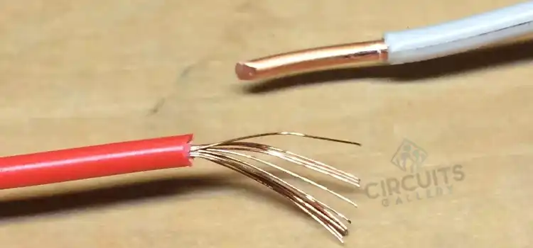
• Skip to main content
  • Skip to secondary menu
  • Skip to primary sidebar
  • Skip to footer
Circuits Gallery

Circuits Gallery

All about Electronics and Circuits

  • Home
  • Basics
    • Components
    • Wiring
    • Circuitry
    • Oscilloscope
    • Conductivity
  • Project
    • Using 555 Timer
    • Using Op-Amp
  • MicroController
    • PIC
  • Arduino
  • Simulation
  • Digital
  • Communication
  • How To
  • About Us

Can You Mix Solid and Stranded Wire? | Compatibility and Safety Guide

June 15, 2023 by Charles Clark Leave a Comment

It is typically possible to mix solid and stranded wire in the same electrical circuit. However, there are important considerations to keep in mind regarding compatibility, current-carrying capacity, and proper connections. 

In this article, we will provide a concise answer to the question of whether you can mix solid and stranded wire, along with the key factors to consider for a safe and effective electrical installation.

Can You Mix Solid and Stranded Wire

Factors to Consider

When it comes to mixing solid and stranded wire, several considerations need to be taken into account. 

Electrical Considerations

The main electrical concern is the difference in the wire’s current-carrying capacity and resistance.

Current-Carrying Capacity

The current-carrying capacity of wires refers to the maximum amount of electrical current that a wire can safely carry without exceeding its temperature rating or causing an excessive voltage drop. 

Solid wire has a higher current-carrying capacity than the stranded wire of the same gauge. Because the solid conductor provides a continuous path for electrical current. On the contrary,  stranded wire with its multiple smaller strands offers increased flexibility but has a slightly lower current-carrying capacity. 

Resistance and Surface Area

Another factor to consider is the difference in resistance between solid and stranded wire. The formula of resistance R of a cylinder is R=ρLA, where ρ is the resistivity of the material, of length L and cross-sectional area A.

Stranded wire has a larger surface area due to the multiple strands, so the solid wire has lower resistance than the stranded wire of the same gauge. This is due to the uninterrupted flow of current through the solid conductor.

Resistance Range

As an example, for solid copper wire, the resistance per unit length typically ranges from about 10.4 Ohms per kilometer (6.46 Ohms per mile) for a 20 AWG wire to 0.00159 Ohms per kilometer (0.00098 Ohms per mile) for a 4/0 AWG wire.

While a 20 AWG stranded wire may have a resistance of about 10.4 Ohms per kilometer (6.46 Ohms per mile),  a 4/0 AWG stranded wire may have a resistance of about 0.00159 Ohms per kilometer (0.00098 Ohms per mile).

Skin Effect

At higher frequencies, alternating currents tend to flow more toward the outer surface of the wire. This phenomenon is known as the ‘Skin Effect’. As stranded wires have multiple strands, it mitigate the skin effect better than solid wire, allowing for more efficient current carrying in such cases.

Compatibility and Codes

In addition to electrical considerations, it’s vital to examine compatibility and adherence to electrical codes when mixing solid and stranded wire.

Compatibility

Solid and stranded wires are generally compatible and can be used together in the same electrical circuit. However, it’s crucial to ensure proper connections between the two types of wire. 

For instance, if a solid wire is connected to a stranded wire, it’s recommended to use wire connectors specifically designed for this purpose. These connectors typically have set screws or clamps that can securely hold both types of wire.

Electrical Codes

Electrical codes provide guidelines and standards for safe electrical installations. Different regions may have their specific codes, so it’s essential to consult the relevant codes for your area. 

In most cases, electrical codes do not forbid mixing solid and stranded wire. However, they often require proper connections and may specify the appropriate connectors to use.

Best Practices While Mixing Solid and Stranded Wire

To ensure a safe and reliable electrical installation, here are some best practices to consider when mixing solid and stranded wire:

Proper Connections

Make sure to use the appropriate connectors when connecting solid and stranded wire. This ensures a secure and reliable connection that minimizes the risk of loose connections or electrical faults.

Gauge and Current Rating

Carefully choose the wire gauge and ensure it matches the circuit’s current rating. Consider the current-carrying capacity of both the solid and stranded wire to prevent overheating and potential hazards.

Insulation and Labeling

Use wires with compatible insulation types and labeling. This ensures proper identification and helps prevent confusion during installation or future maintenance.

Frequently Asked Questions

Is It to Mix Solid and Stranded Wire in the Same Circuit?

While it is generally not recommended to mix solid and stranded wire within the same circuit, there are certain scenarios where it can be acceptable. However, it’s important to follow the guidelines and regulations set forth by electrical codes and standards in your region.

To Conclude

When combining solid and stranded wire it’s crucial to ensure that the circuit is designed to handle the maximum current required. Failure to do so may result in overheating and potentially dangerous situations. Additionally, proper connections, adherence to electrical codes, and following best practices are essential for a safe and reliable electrical installation.

Filed Under: Basics, Wiring

Reader Interactions

Leave a Reply Cancel reply

Your email address will not be published. Required fields are marked *

Primary Sidebar

More To See

How Far Can You Run Low Voltage Lighting

How Far Can You Run Low Voltage Lighting? Exploring the Limits of Low Voltage Lighting Installations

What is the Difference between RC Coupling and Transformer Coupling

What is the Difference between RC Coupling and Transformer Coupling? In-Depth Guide

Oscilloscope Probe X1 X10 Difference

Oscilloscope Probe X1 X10 Difference | Detection and Compensation of Probes

How to Measure Amps on 240V Circuit With Multimeter

How to Measure Amps on 240V Circuit With Multimeter | Step-By-Step Guide

More About

  • Arduino
  • Basics
  • Circuitry
  • Communication
  • Components
  • Conductivity
  • Digital
  • How To
  • MicroController
  • Oscilloscope
  • PIC
  • Project
  • Simulation
  • Using 555 Timer
  • Using Op-Amp
  • Wiring

Footer

QUICK LINKS

  • About Us
  • Privacy Policy
  • Terms and Conditions
  • Contact

AFFILIATE DISCLOSER

Circuits Gallery is a participant in the Amazon Services LLC Associates Program, an affiliate advertising program designed to provide a means for website owners to earn advertising fees by advertising and linking to amazon (.com, .co.uk, .ca etc) and any other website that may be affiliated with Amazon Service LLC Associates Program

© 2023 · Circuits Gallery | All Rights Reserved