Welcome to Circuits Gallery
Let’s Upgrade your Electronics knowledge with the latest and greatest CG tips and guides
The story of Circuit Gallery is quite a funny one. During our college years, we had to fix a ceiling fan. It was our first-hand experience of how wiring an electric device wrong would turn it into a total disaster. After that incident, some like mind friends set up a goal to educate people about circuit boards, electric connections, DIY soldering, and much more. And Circuits Gallery was born…
We are featured on
We’re proud to have been featured by some of the world’s leading organizations. These features highlight our excellence in the field of Electronics Knowledge. Here are a few of the organizations that have recognized our work


 Browse Categories
Find Popular topics for your circuit needs:
Recent Blogs
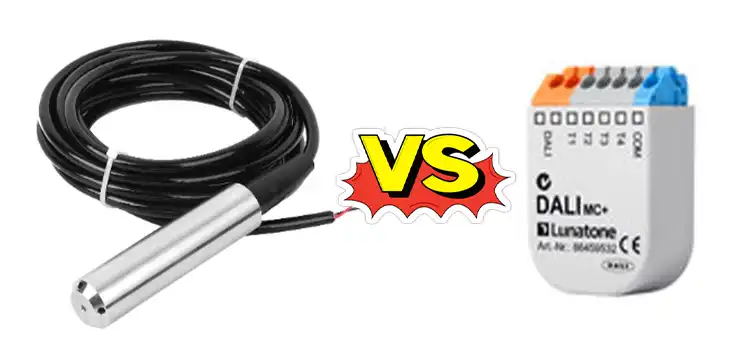
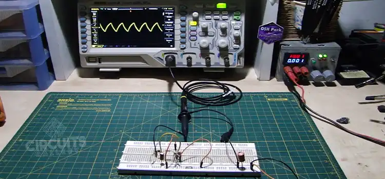
4-20mA vs 0-10V | ULTIMATE COMPARISON
The 4-20mA signal, a current loop standard, offers higher accuracy and noise immunity, making it suitable for industrial environments, while the 0-10V signal, a voltage-based…

From Ceiling Fan Fiasco to Circuit Champions: Circuits Gallery Demystifies Electronics
Ever stared at a jumbled mess of wires and resistors, completely bewildered with the aid of how they strengthen your favorite gadgets? We at Circuits…
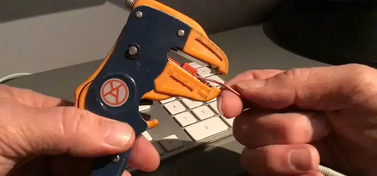
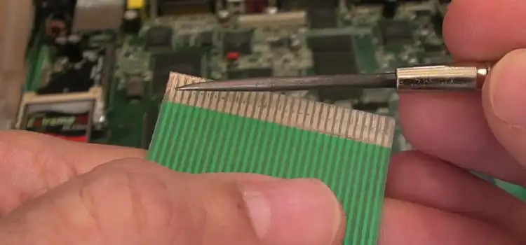
How to Strip Ribbon Cable | 3 Ways and Tips
Ribbon cables, with their flat, multi-wire structure, are commonly used in electronic devices and computer systems to transmit data and signals between components. Stripping these…
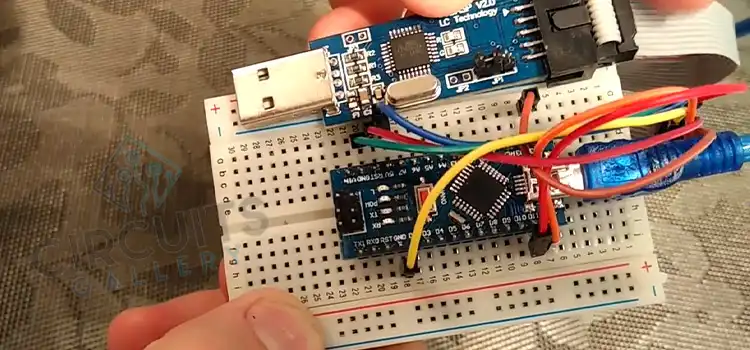
How to Solder Ribbon Cable | Mastering the Art of Soldering
Whether you’re connecting ribbon cables to circuit boards, repairing damaged cables, or customizing cable lengths, skillful soldering ensures secure and reliable connections. And to complete…
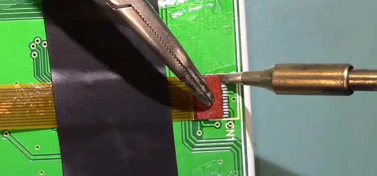
LCD Ribbon Cable Repair Methods | [3 Fixes Detailed]
LCD screens are an essential part of many electronic gadgets, such as televisions, laptops, and smartphones. The ribbon cable that links an LCD’s panel to…
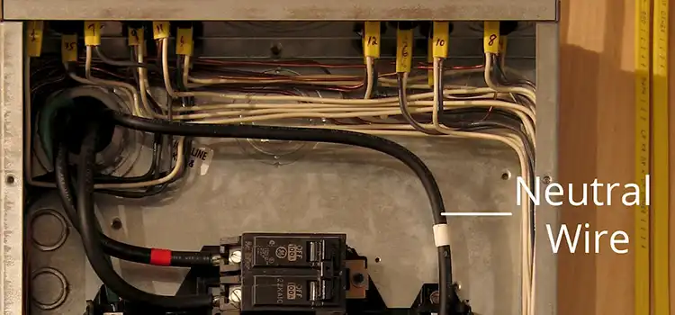
Why Do I Have 120 Volts on My Neutral? A Comprehensive Guide
Electrical systems encountering 120-volt issues on the neutral wire face potential hazards due to various causes and wiring failures. Loose connections in the main panel…
Can’t Find What You’re Looking For?
Need Assistance?
Recent Projects
Feature Your Projects in Circuits Gallery

Circuits Gallery works on –

Experiment
We guide you through hands-on experiments to demystify electronics, regardless of your skill level

Innovate
Stay at the cutting edge with our insights into emerging tech trends and innovative circuit designs
Find Solutions
Count on us for troubleshooting and solutions, making electronic device issues a thing of the past
Circuits Gallery Monthly Numbers
Monthly readers
Circuit Solutions
Creative Projects
How Circuits Gallery Ensure Quality Content?
At Circuits Gallery, a bunch of young EEE engineers invest countless hours in researching, experimenting, and fine-tuning every article. Their dedication ensures that you receive accurate, up-to-date, and reliable information.

Expert Opinions
We start with insights from our Electrical and Electronics Engineers (EEE)

Thorough Research
In-depth research from credible sources informs our content

Editors’ Review
Experienced editors ensure clarity and readability

Publishing
Only after passing these stages do articles earn their place on our site